
Shielded cables
Overall and individually screened power, control, VFD and medium-voltage cables from 300/500 V to 35 kV for EMC protection and electric-field control.
How does the cable move?
Pick one or more duties — the list below updates.
54 shielded cables
Low-voltage range
Up to 0.6/1 kV for industrial power, control and mobile equipment.
11 cables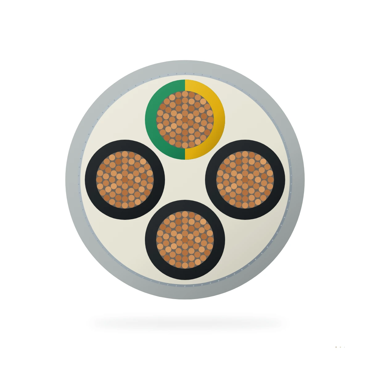
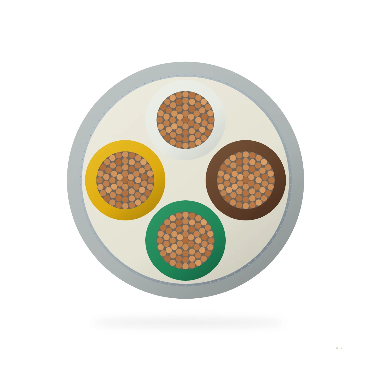
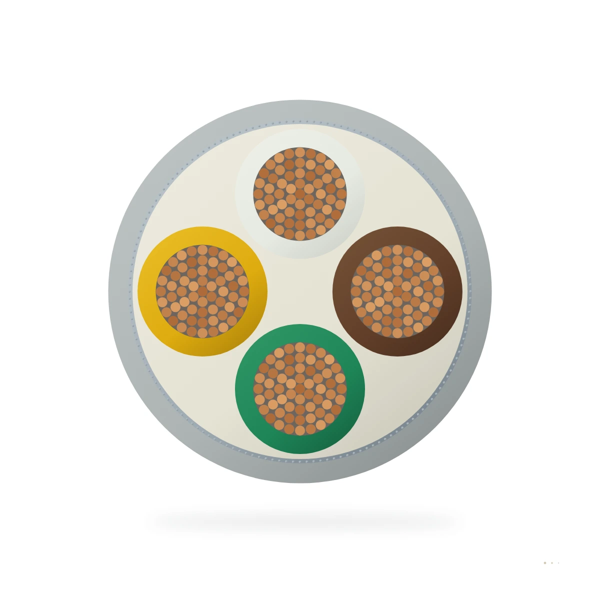
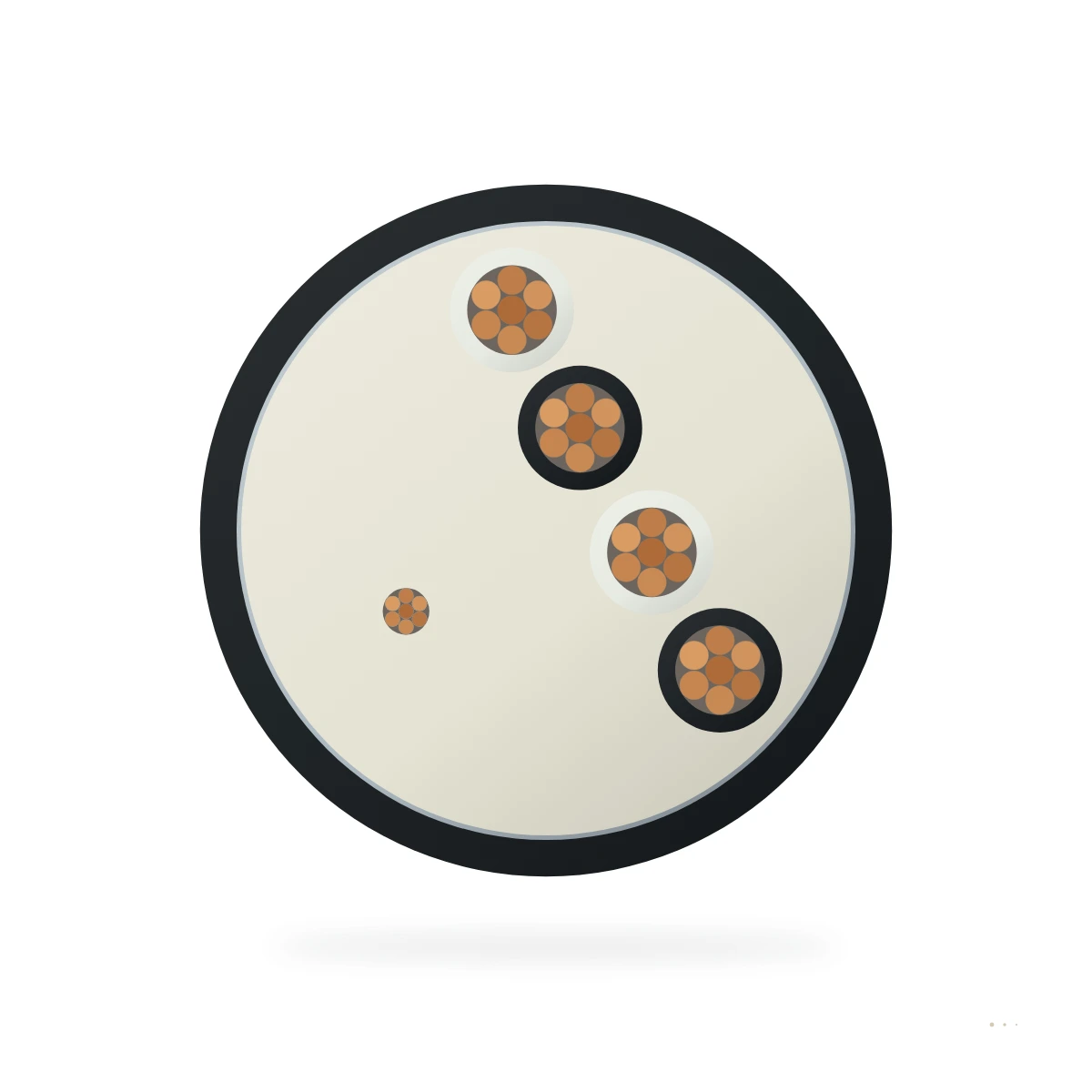
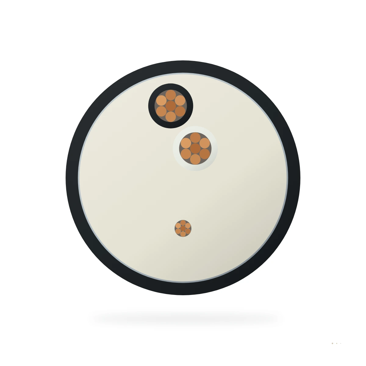
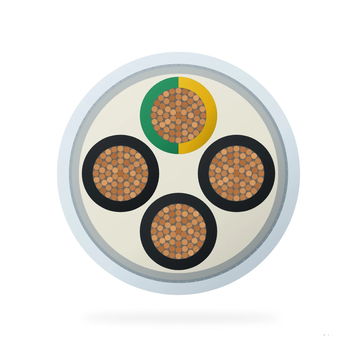
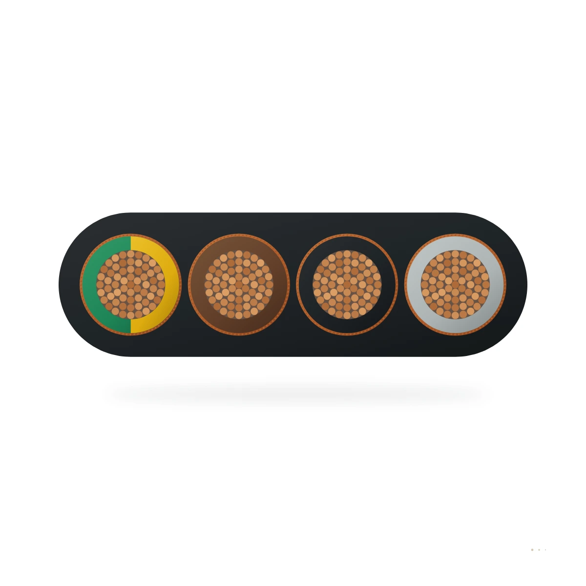
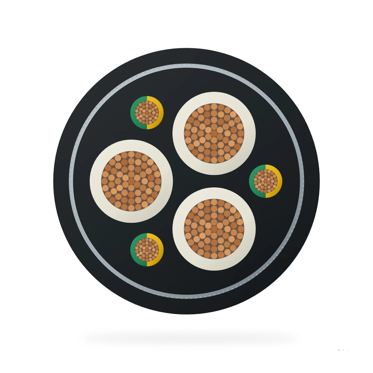
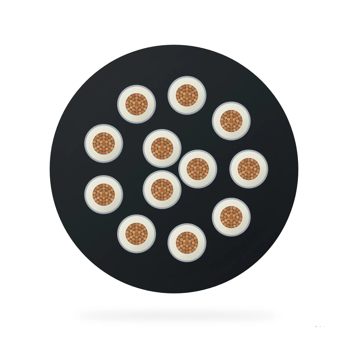
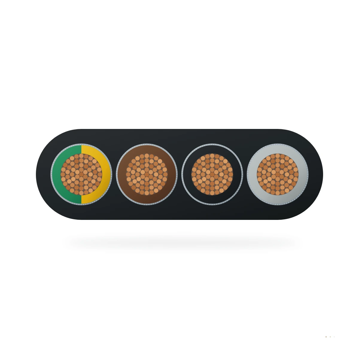
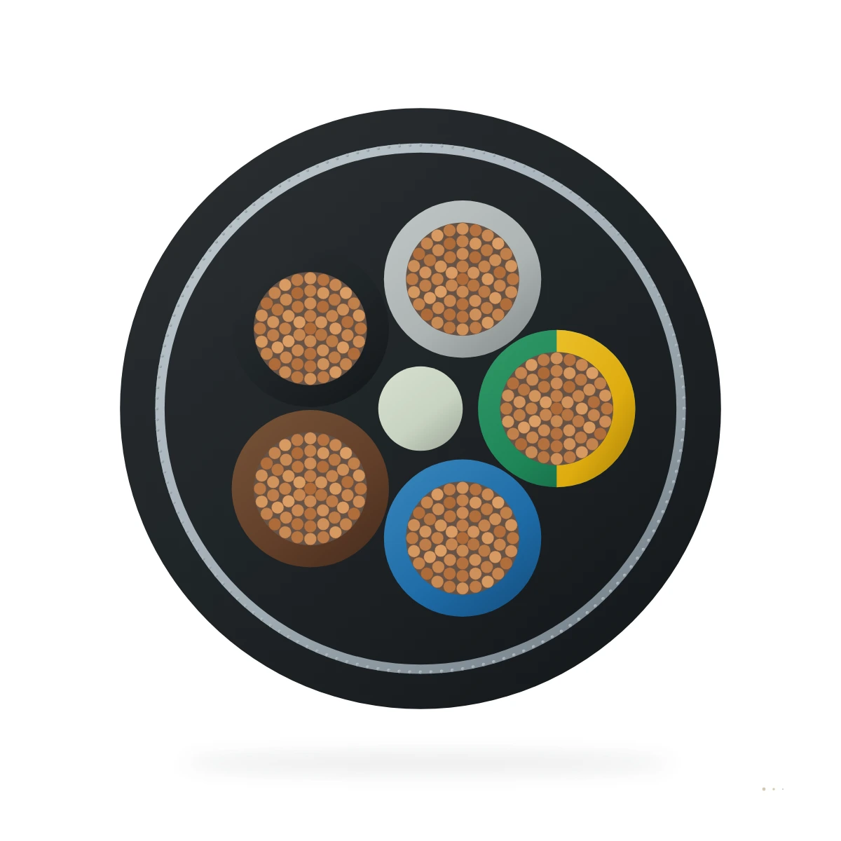
Dynamic & guided motion
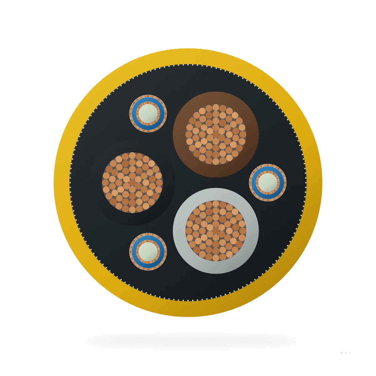
Reinforced constructions for festoon trolleys, energy chains and vertical suspension.
12 cables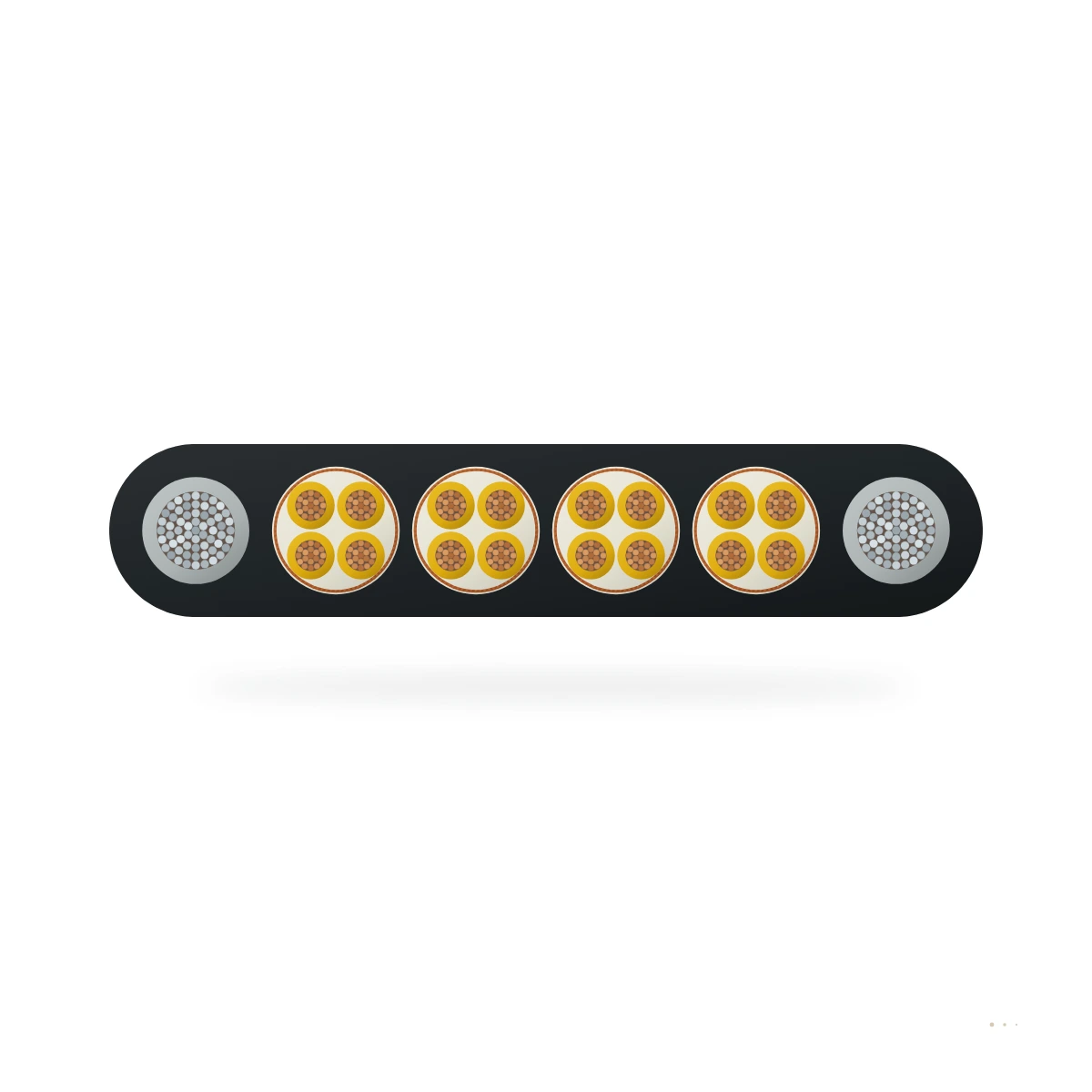
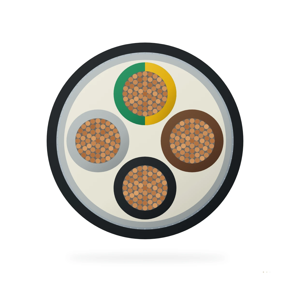
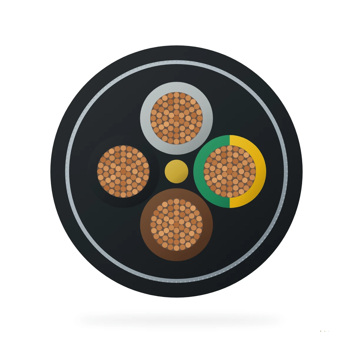
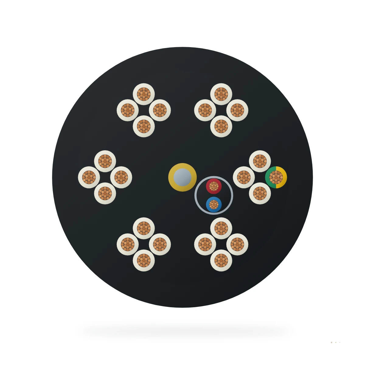
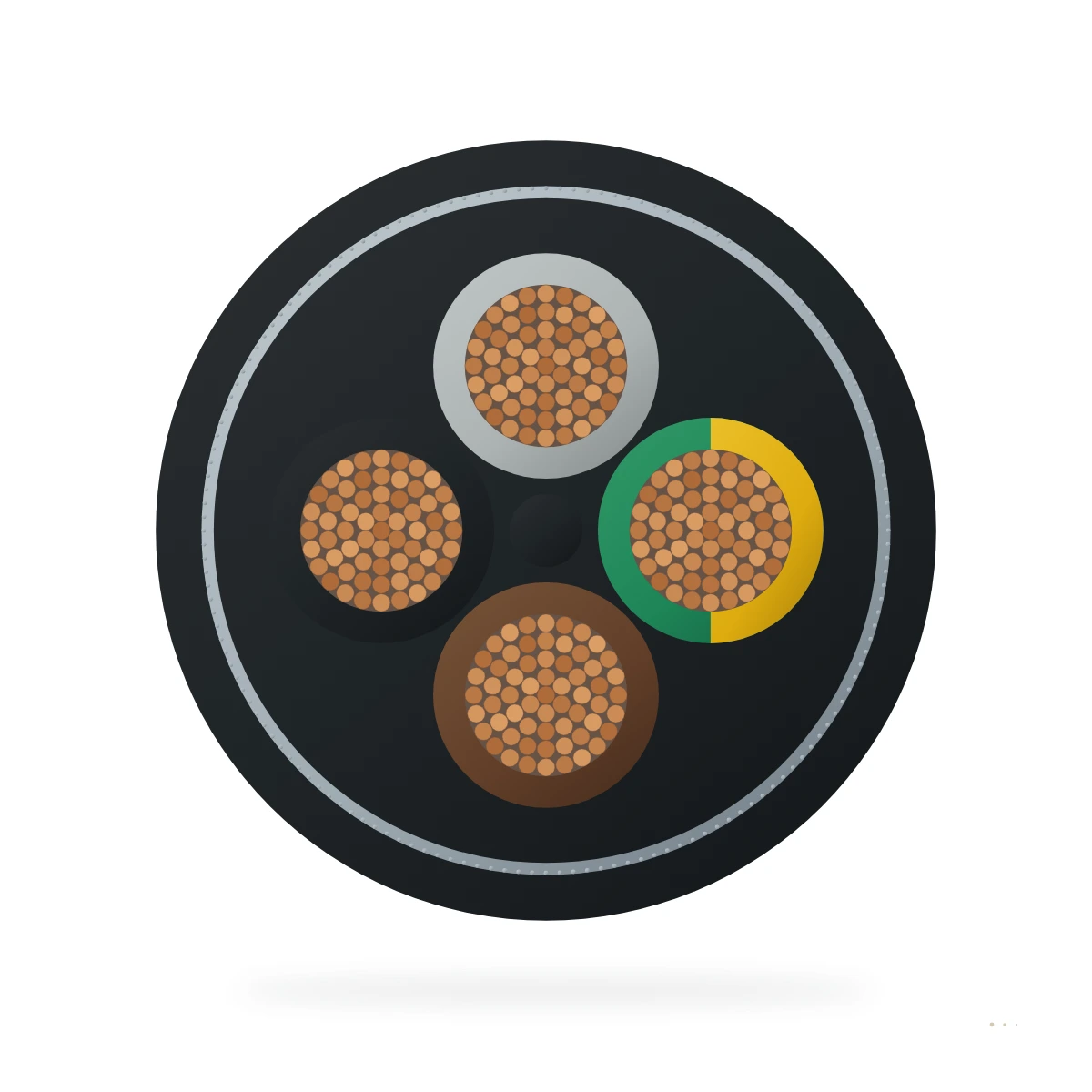
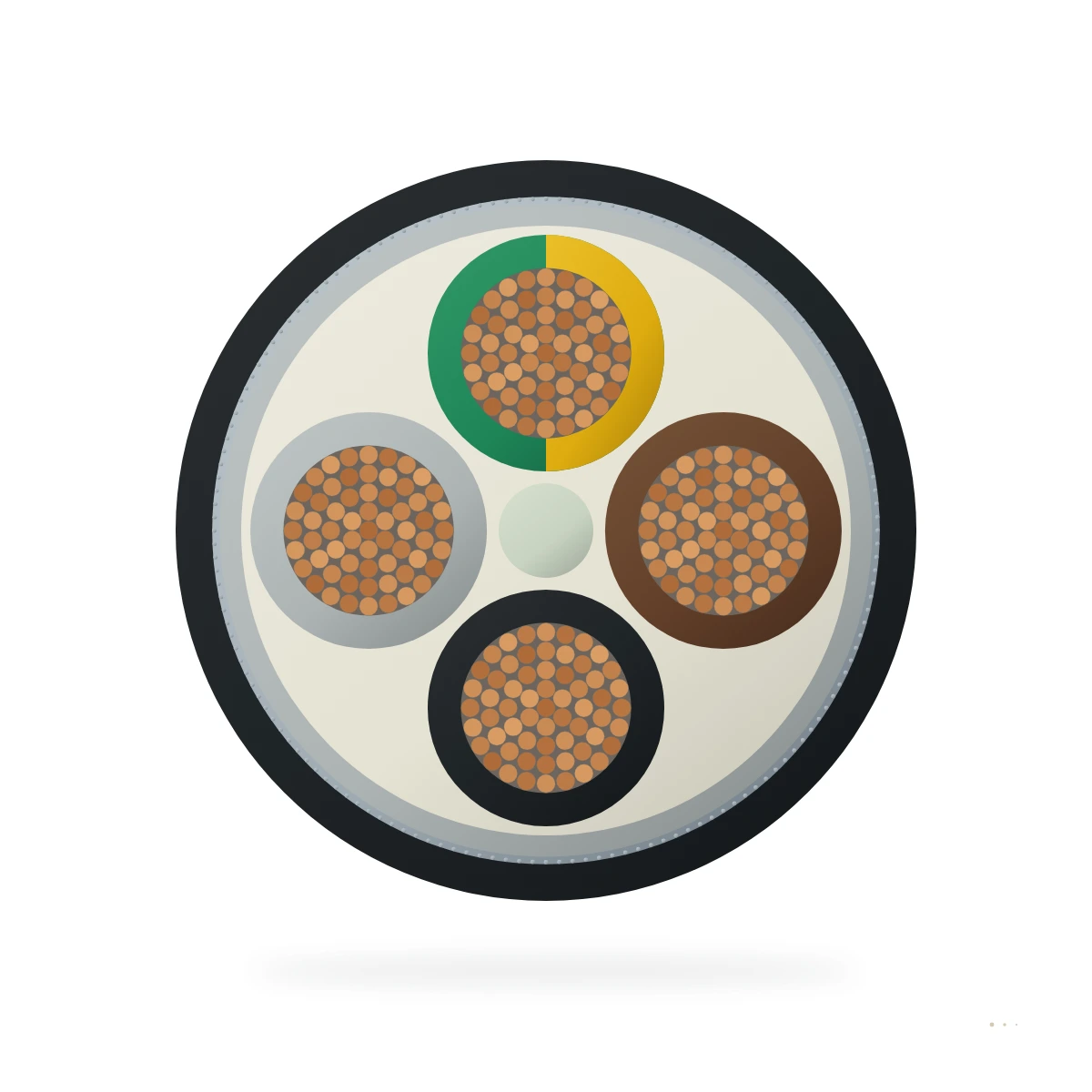
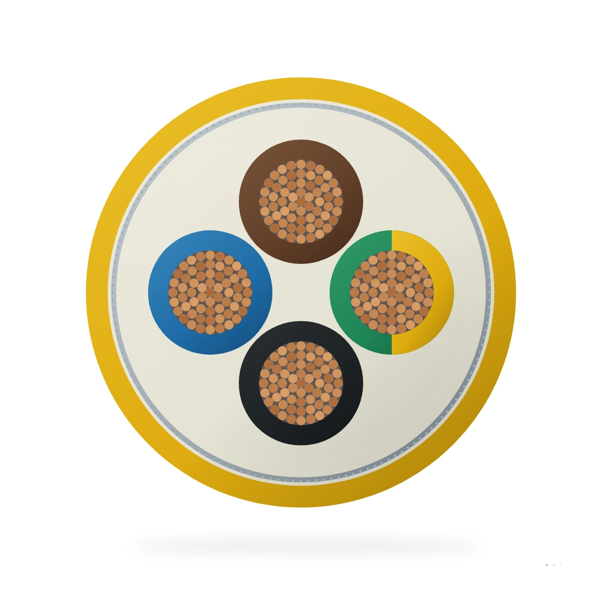
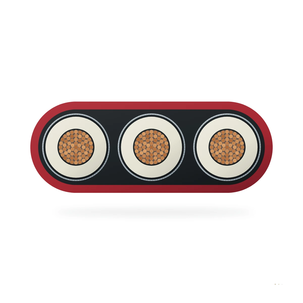
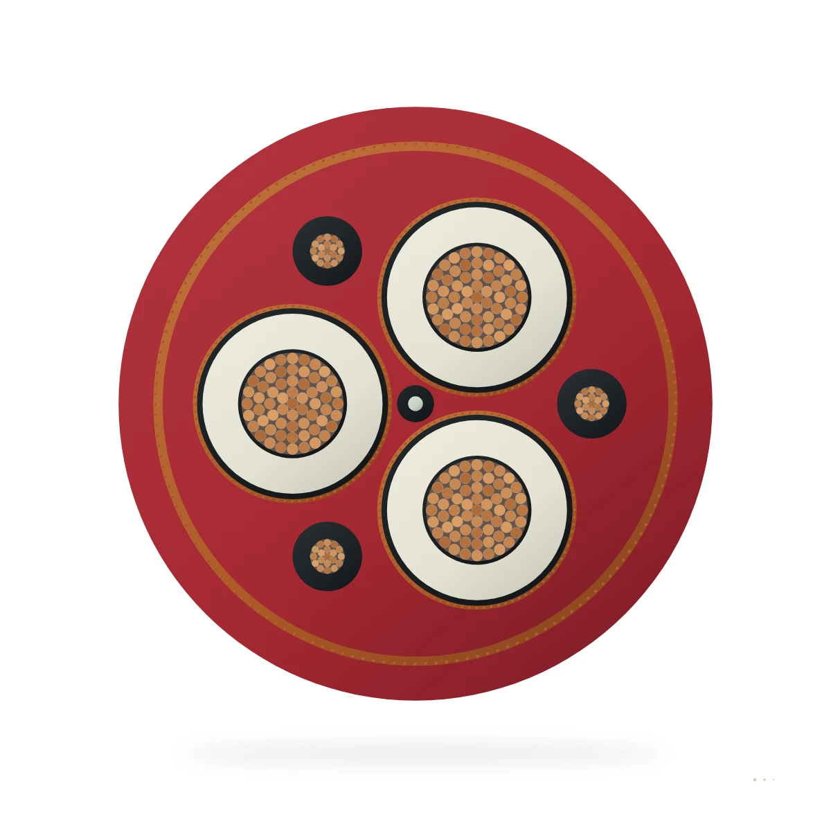
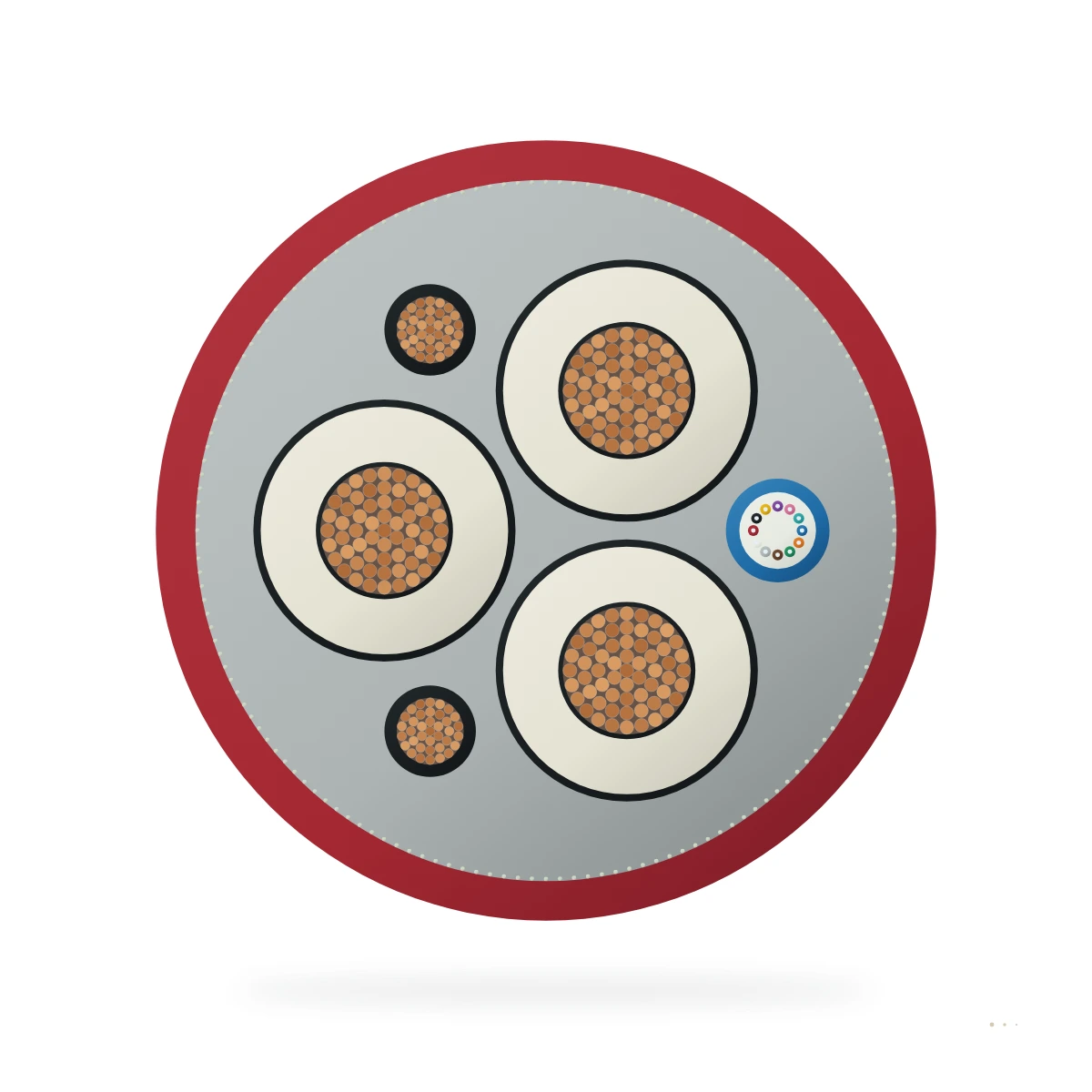
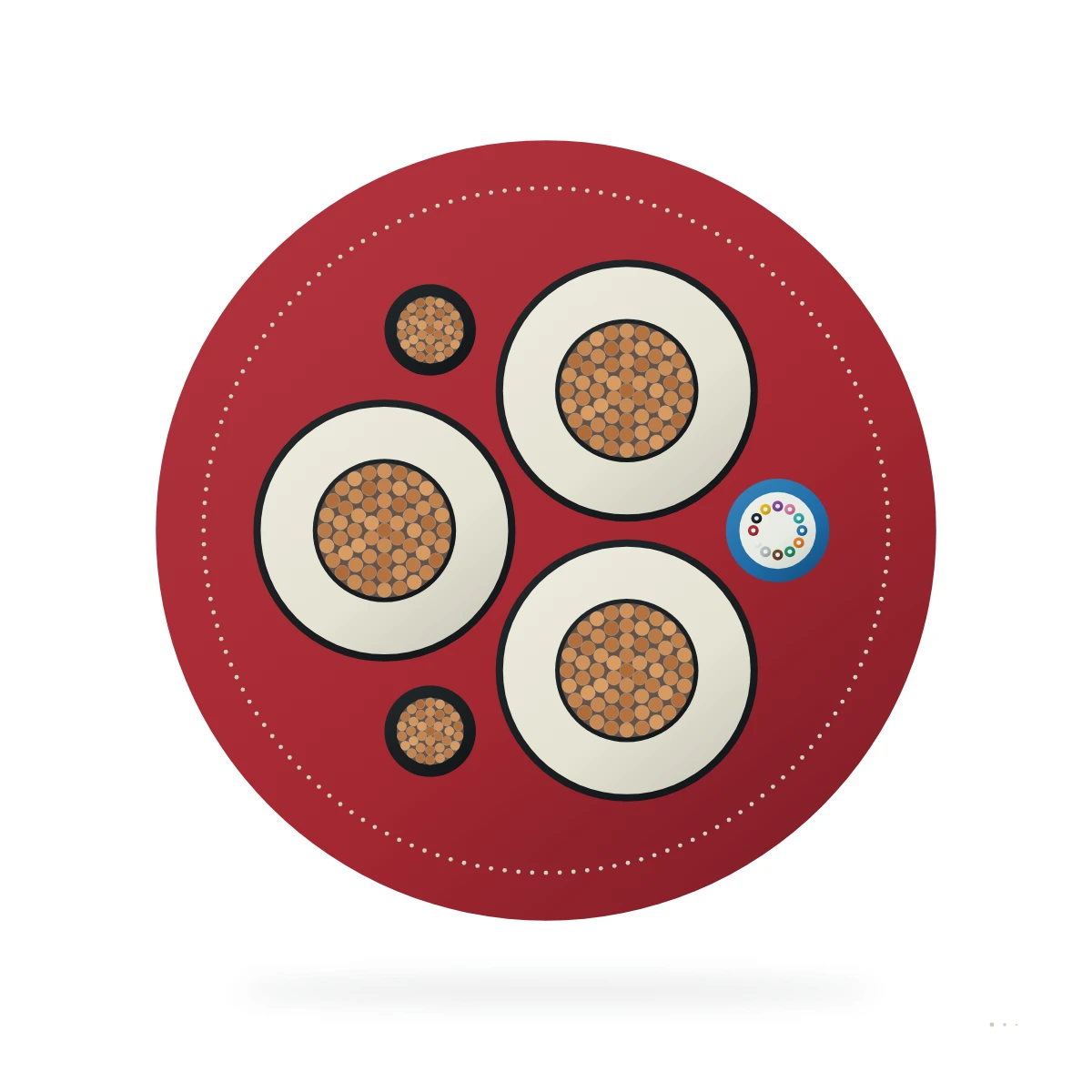
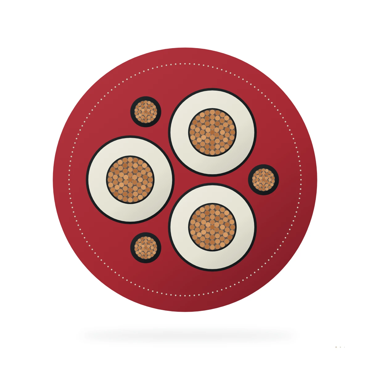
Medium-voltage range
Screened cables from 1.8/3 kV to 35 kV with semiconductive field control.
11 cables
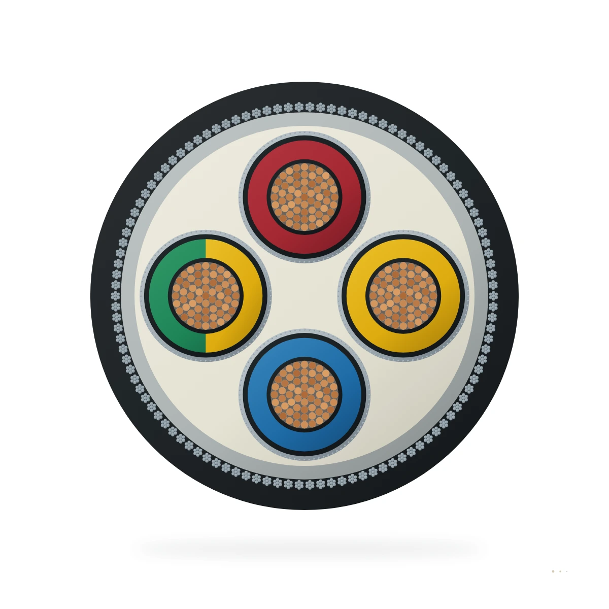
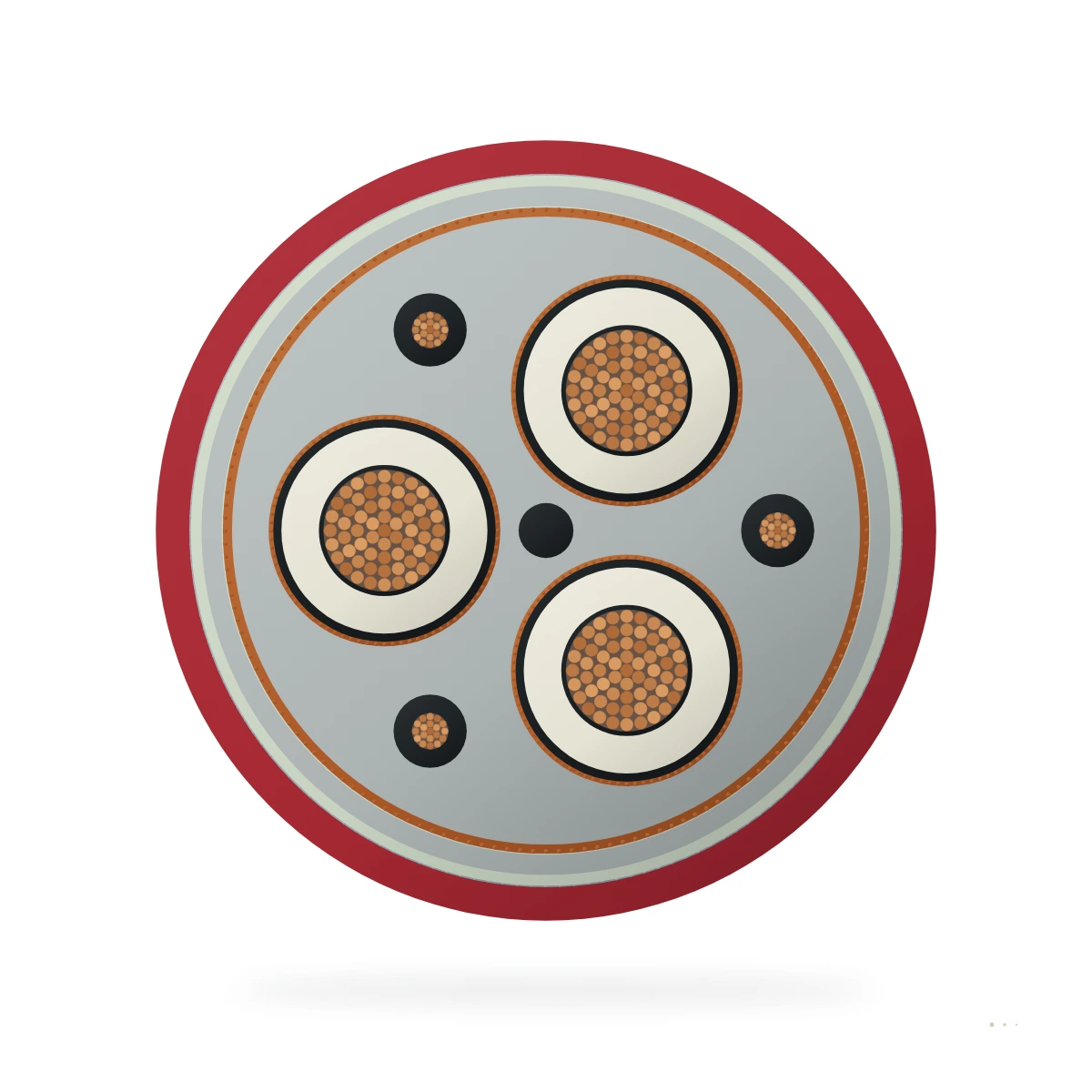
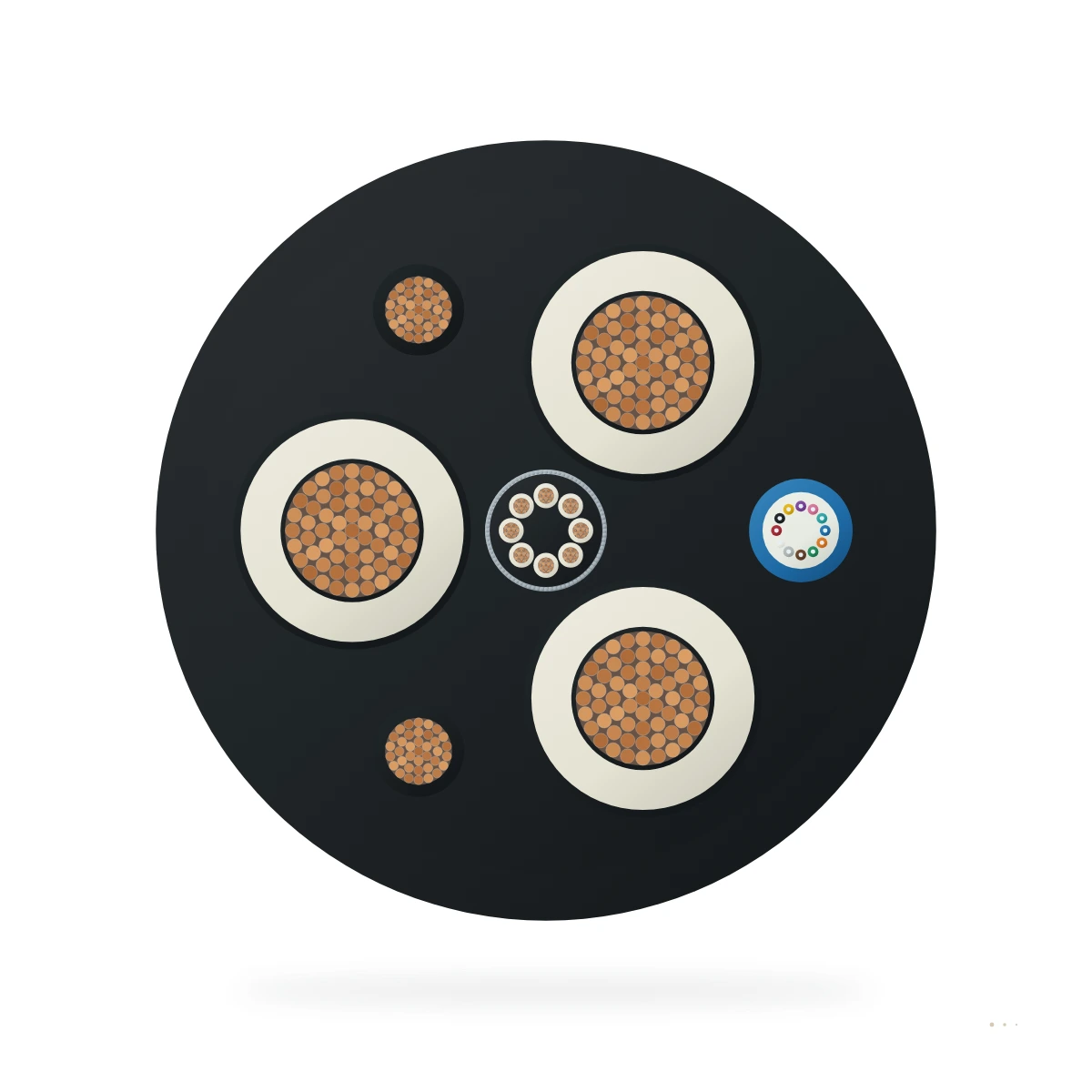
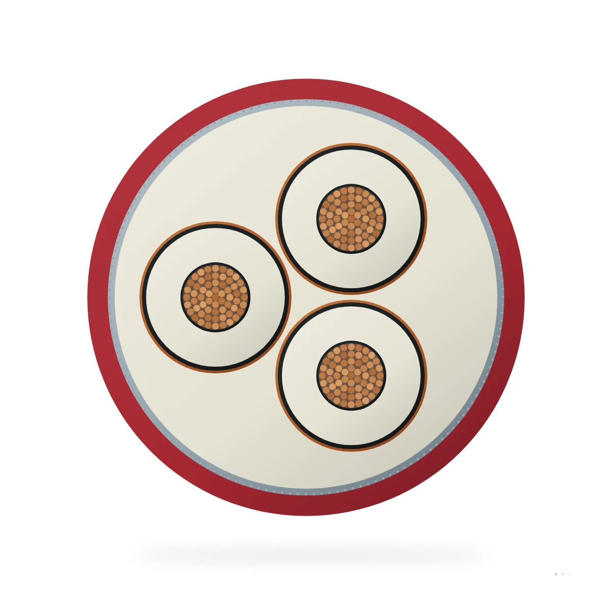
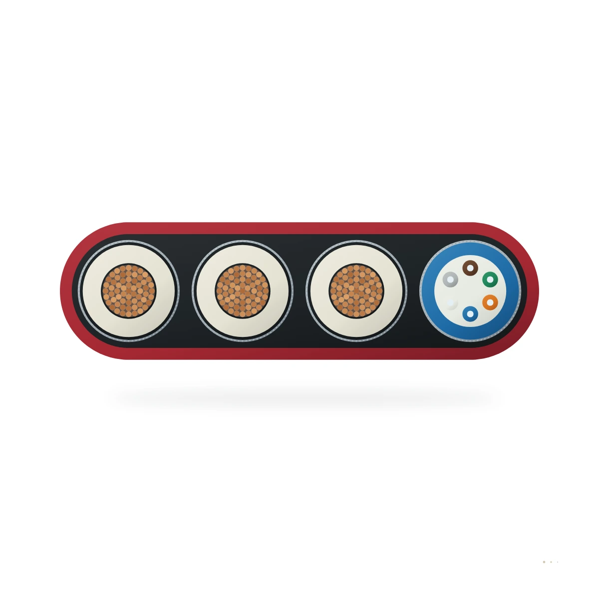

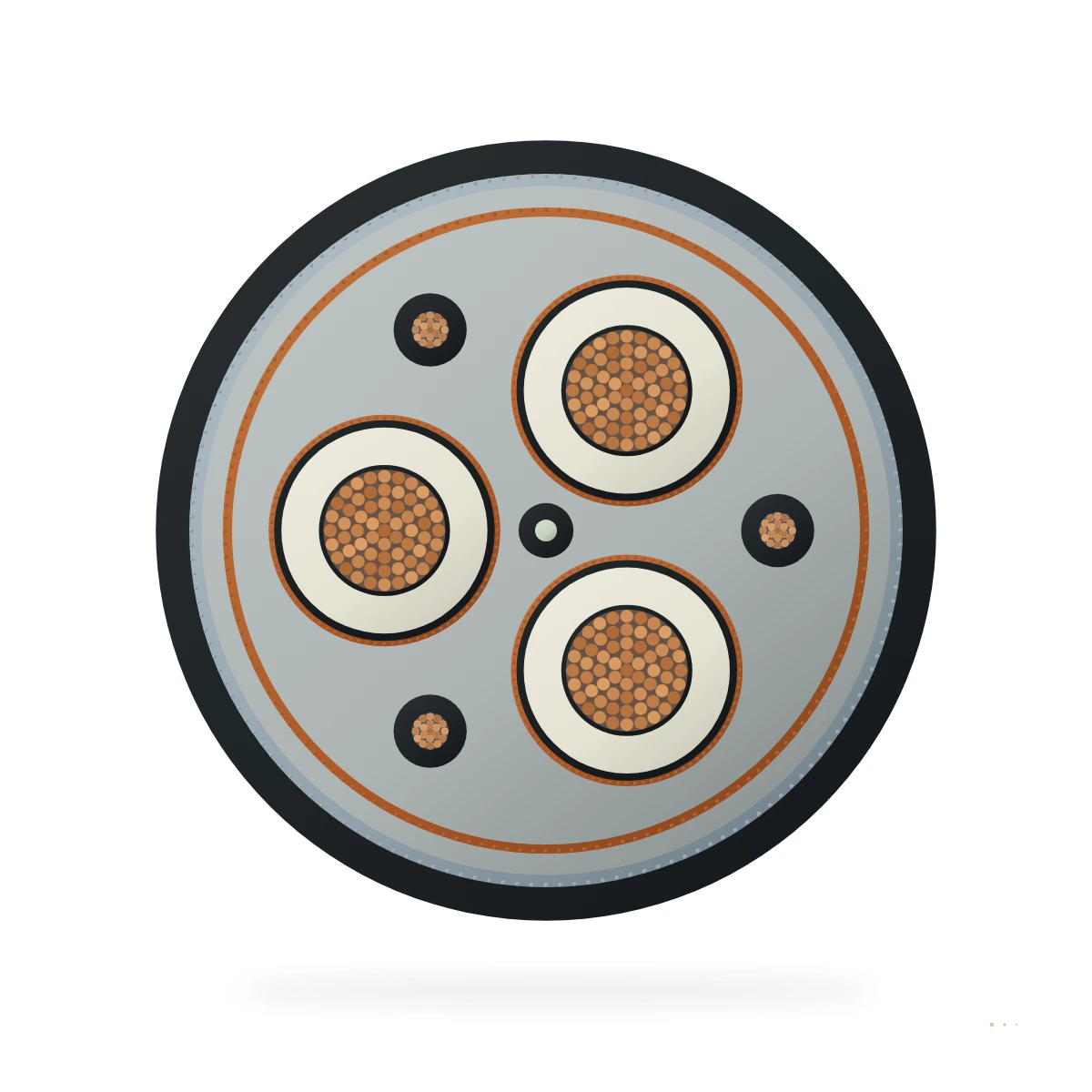
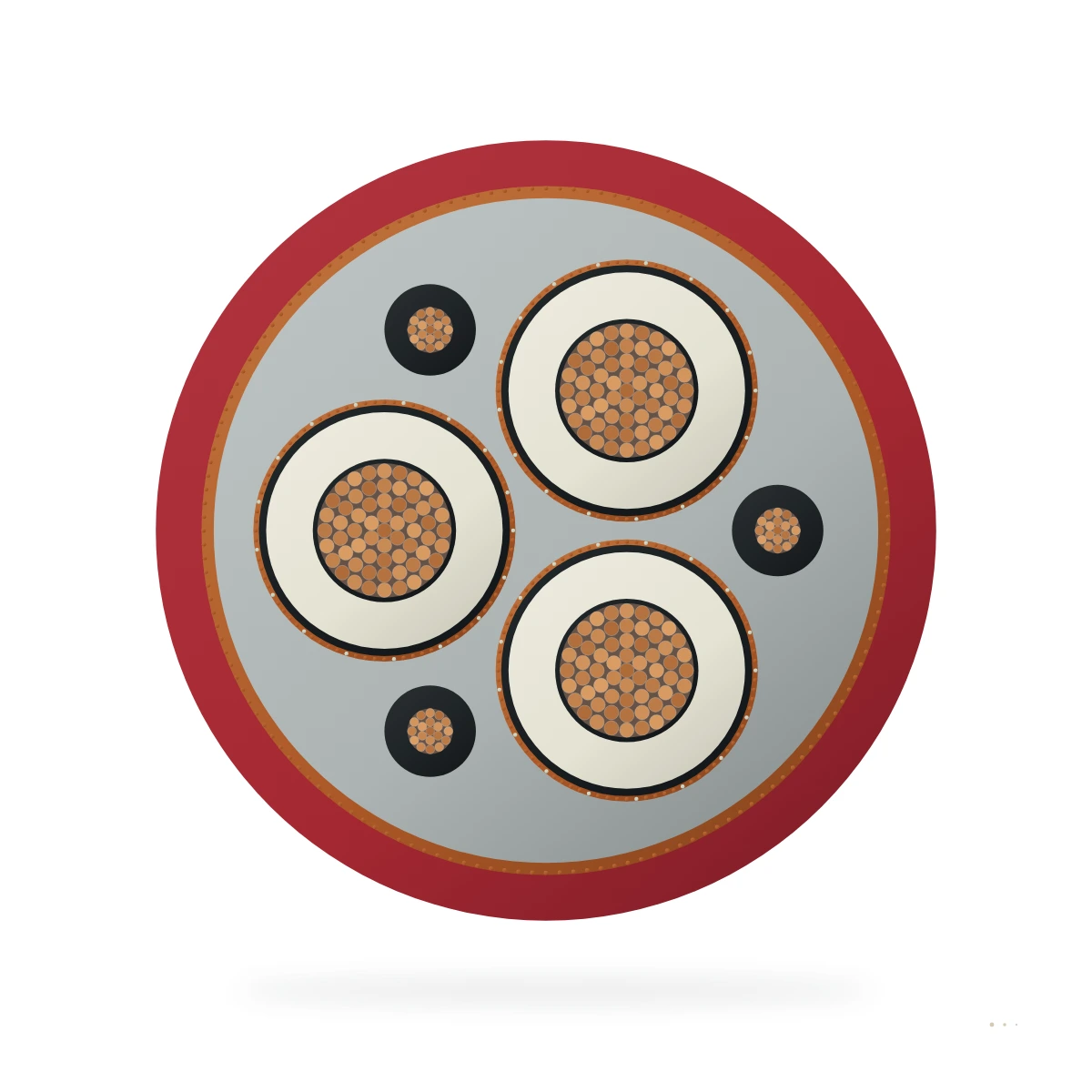
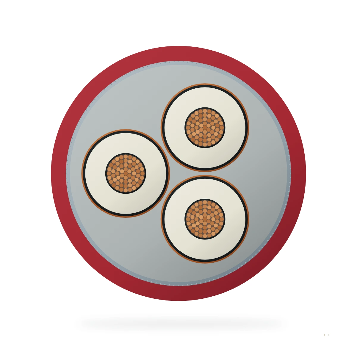
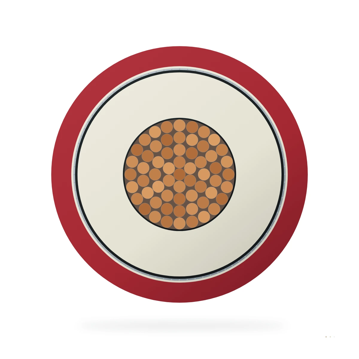
Mining & tunnelling
Heavy-duty trailing, reeling and roadway feeder cables to DIN VDE, ICEA, BS and SANS.
16 cables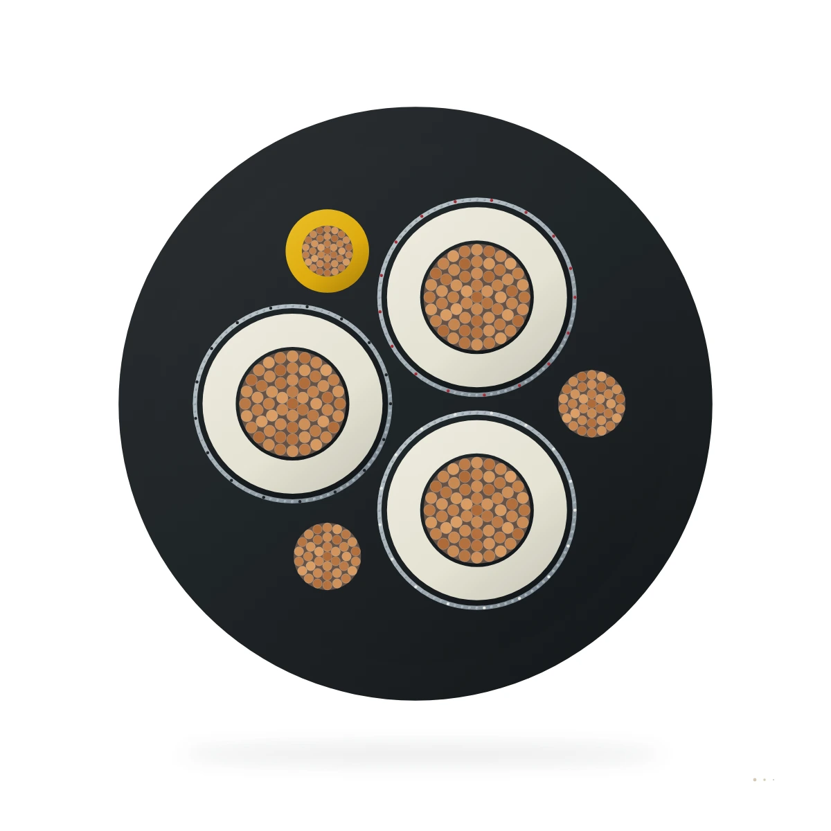
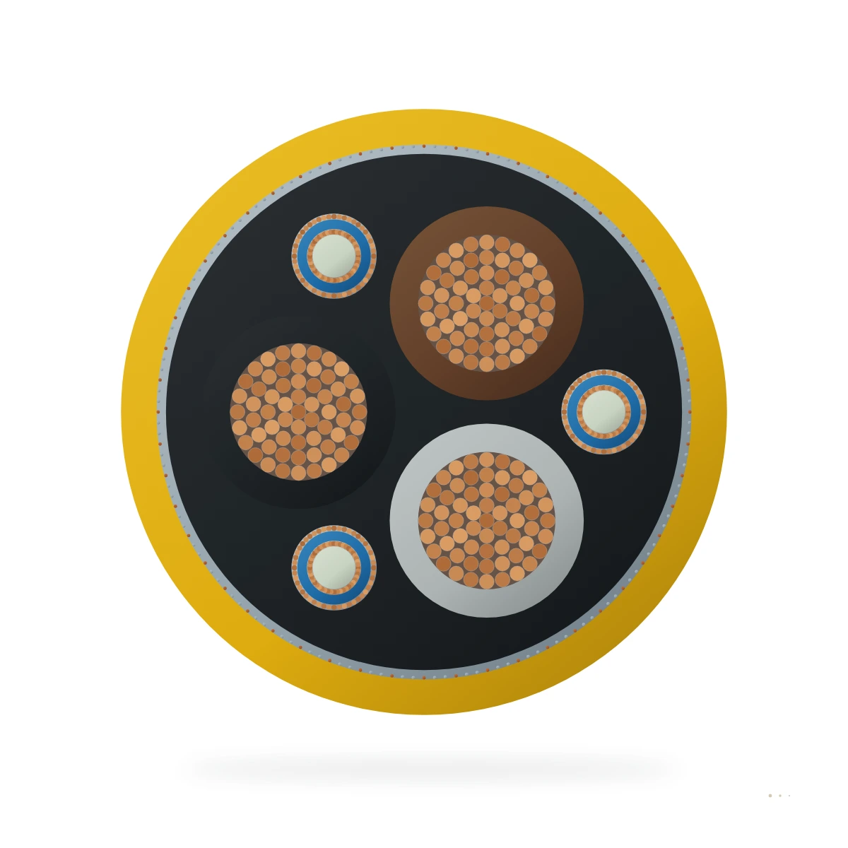
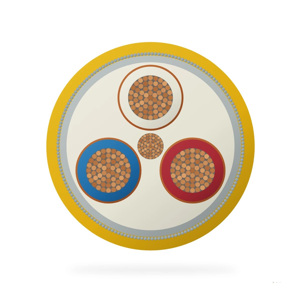
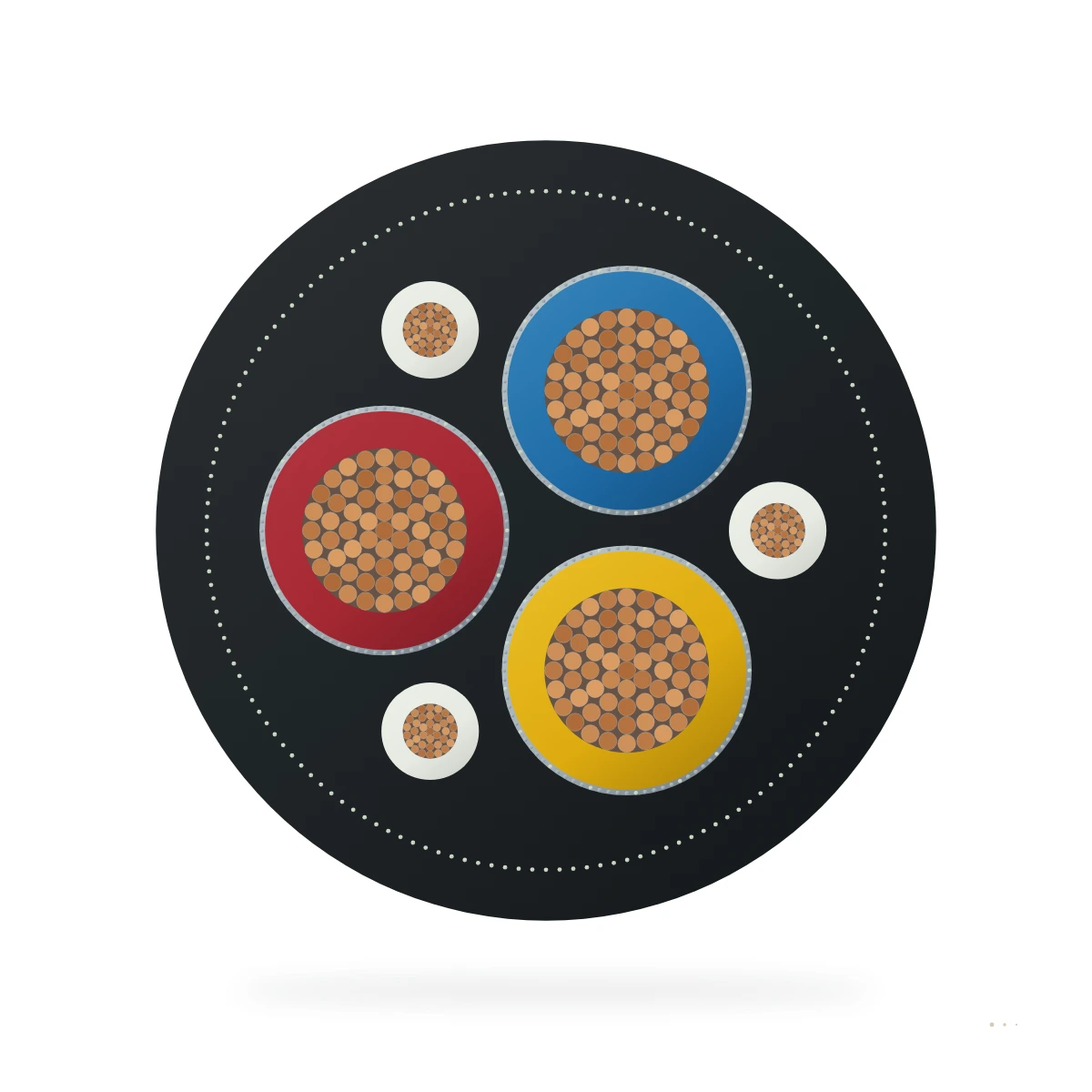
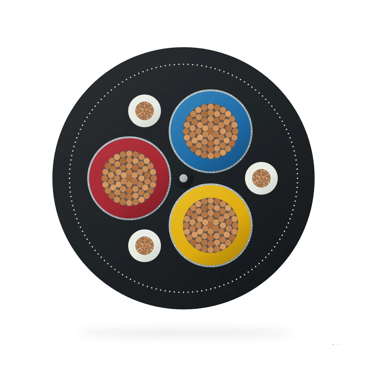
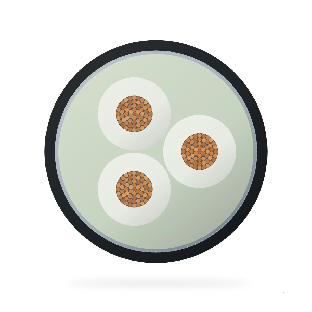
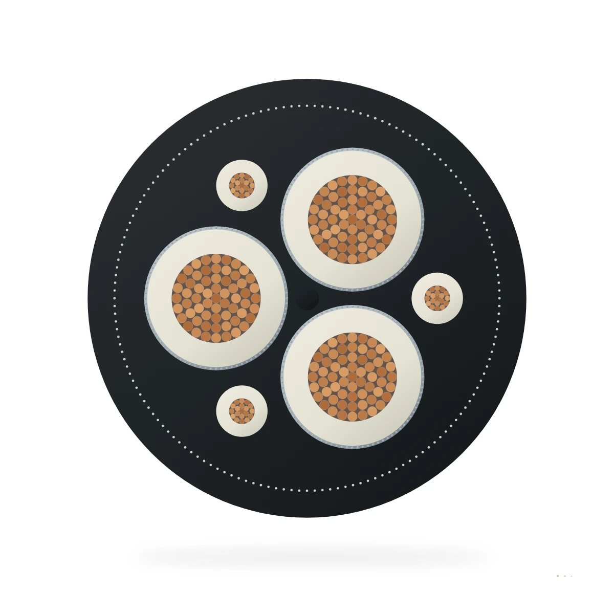
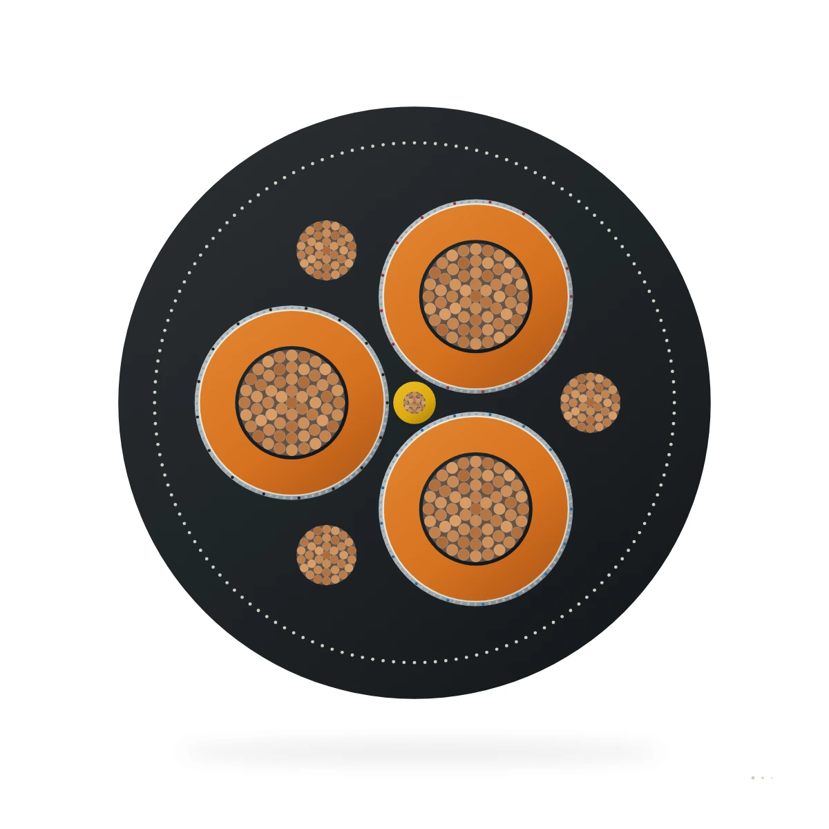
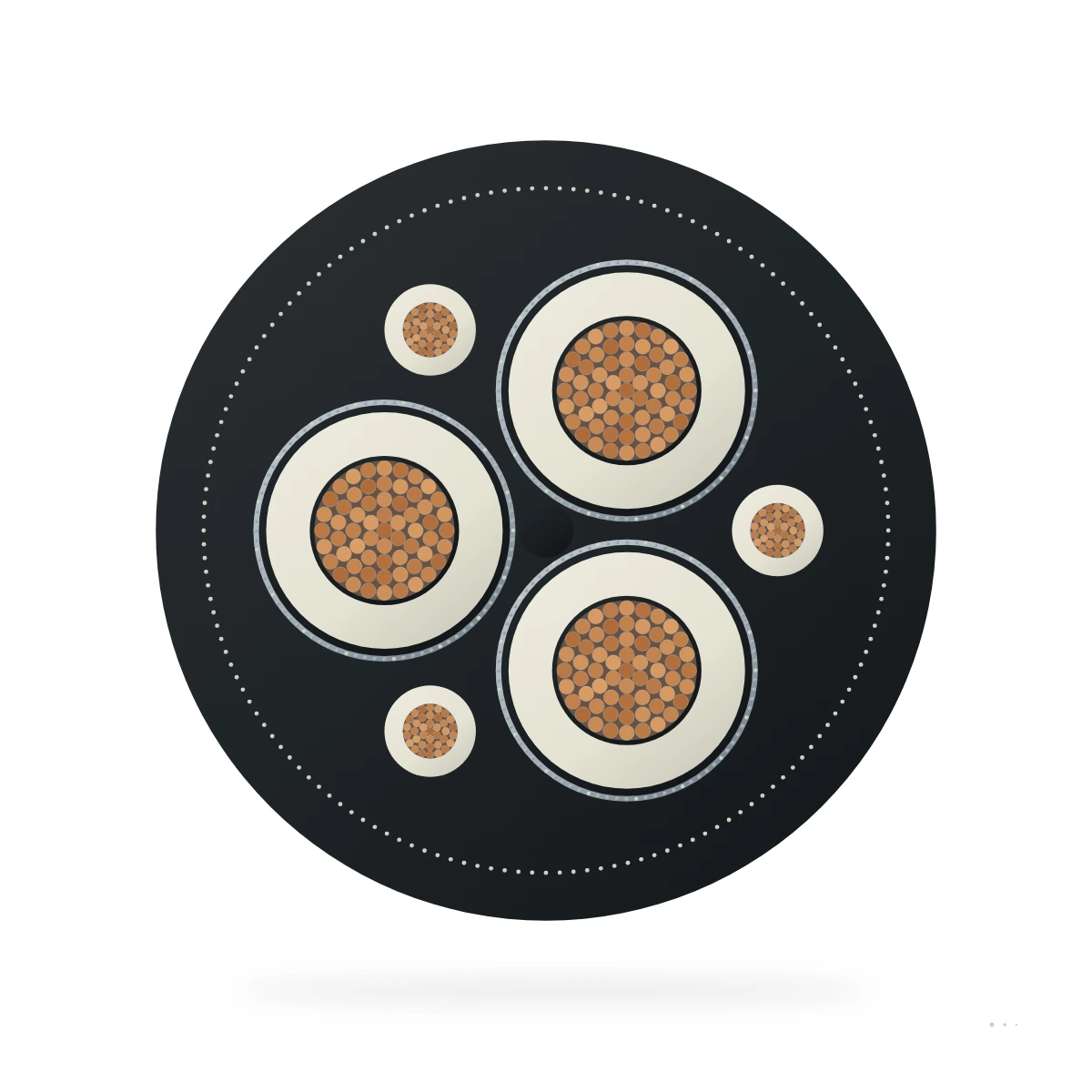


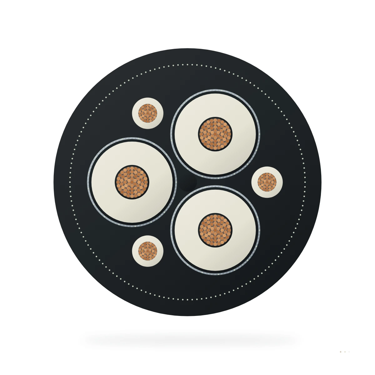
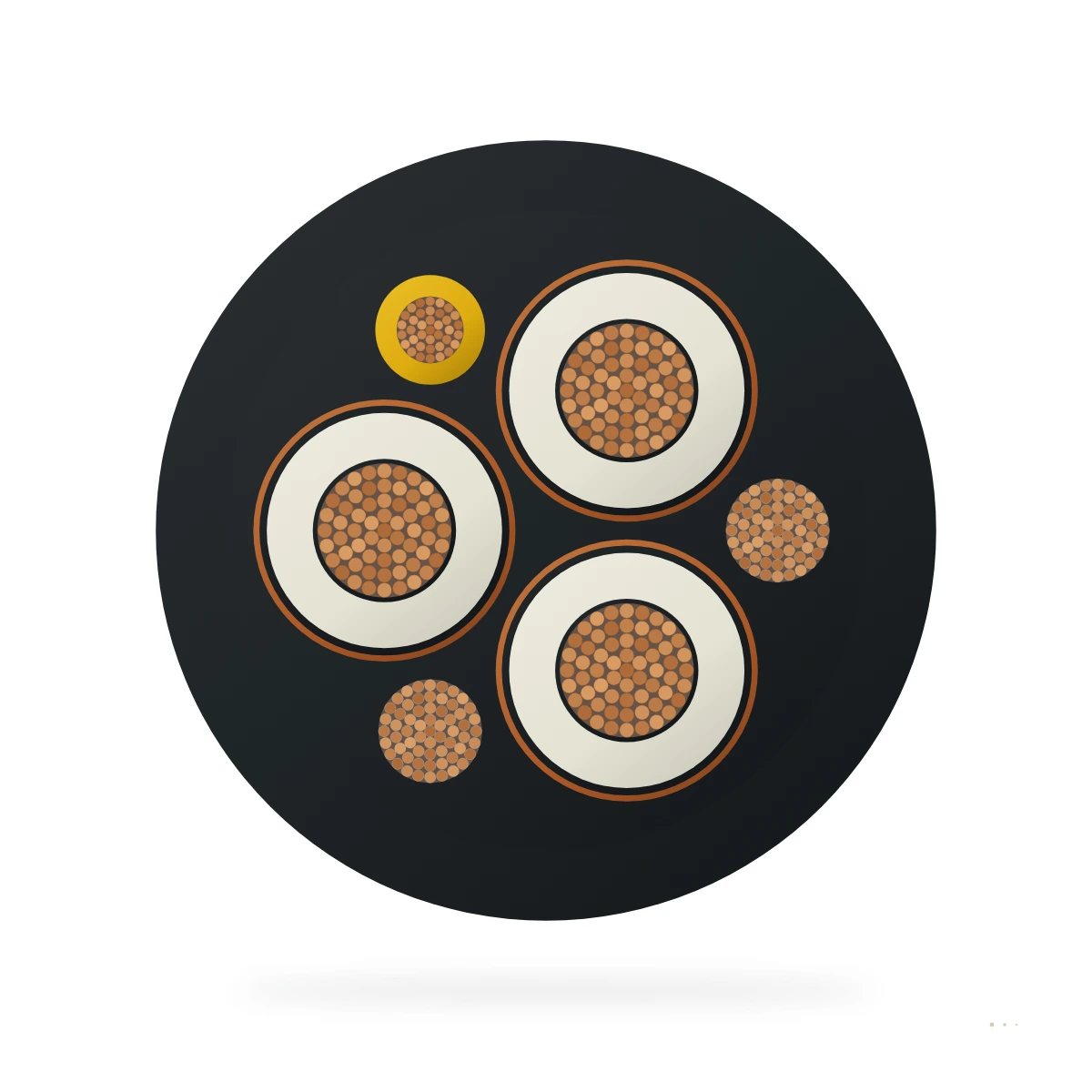
Marine & offshore
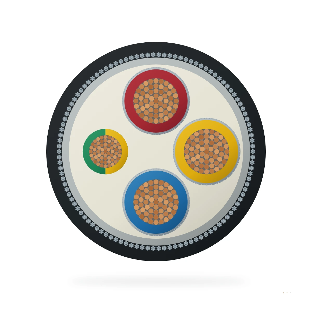
Shipboard and offshore platform cables built to IEEE 1580, NEK 606 and BS standards.
2 cables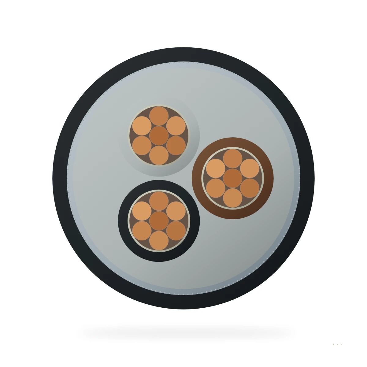
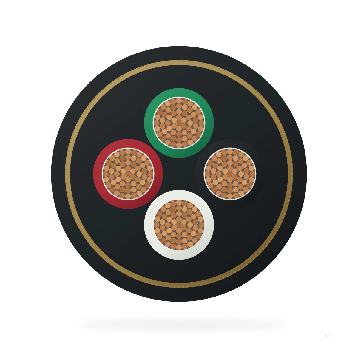
Screened VFD & motor feeders
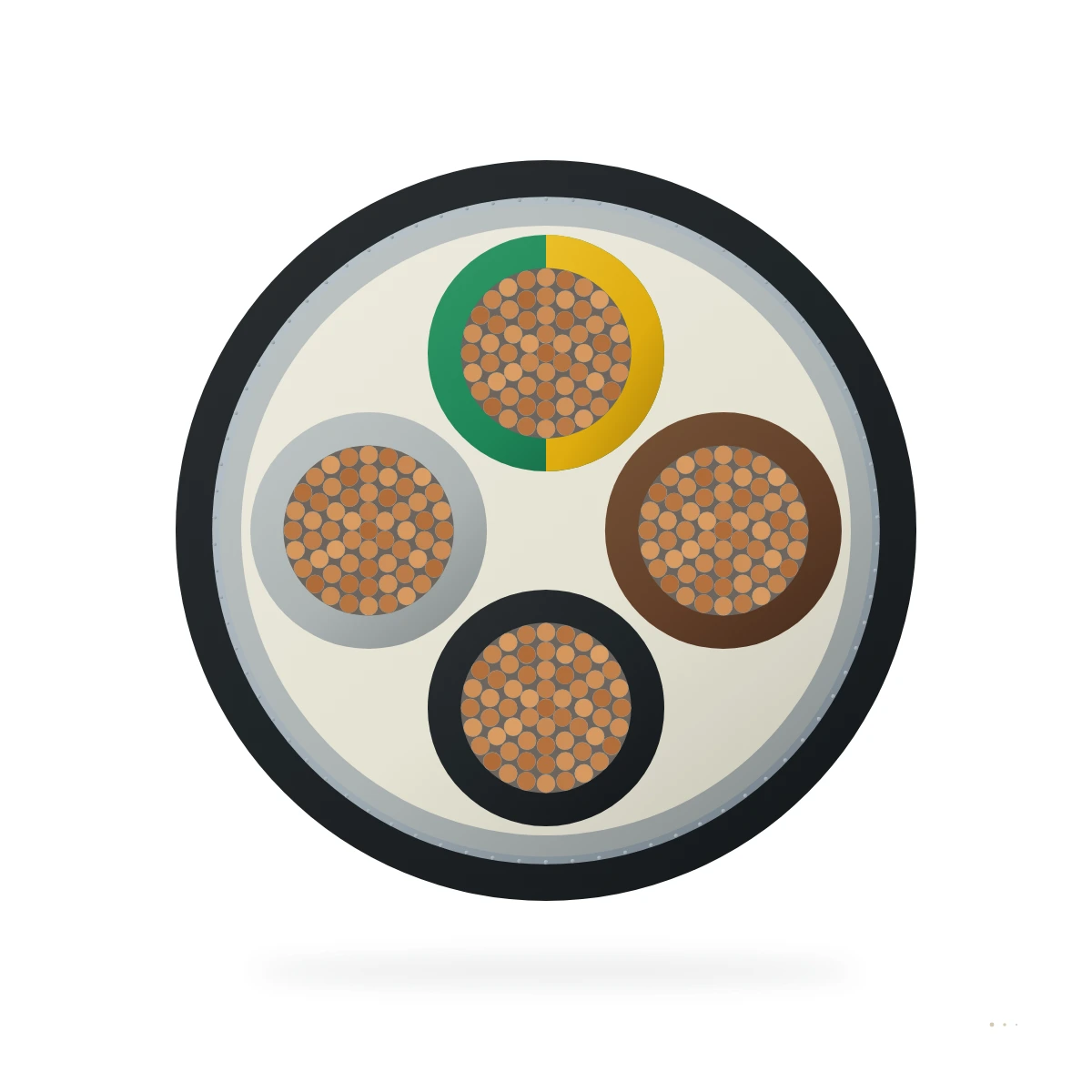
Low-impedance screened cables for variable-frequency drives and AC traction motors.
2 cables
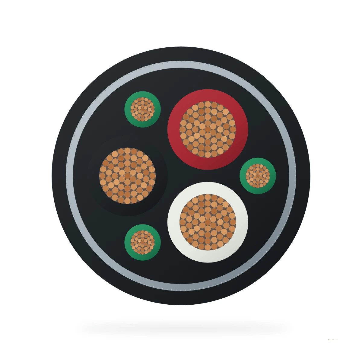
Choosing shielded cables
Four things decide most selections. Our engineers check the rest against your application.
Application and movement duty
- Define whether the cable runs in a fixed tray, energy chain, festoon loop, reel or trailing route.
- Match travel speed, bend radius and tensile load to the mechanical construction.
- Select a support element or armour when the cable carries suspended weight or external crush loads.
Voltage class and core layout
- Match the rated voltage U0/U to the supply system and earthing arrangement.
- Specify phase cross-sections, protective earth, pilot cores or control pairs required by the machine.
- Include copper braid, tape or semiconductive screens where EMC or electric-field control is needed.
Operating environment and sheath
- Choose rubber, PUR, LSZH, PVC, fluoropolymer or silicone sheaths for the thermal and chemical exposure.
- Verify oil, UV, water immersion, cold-flex or circuit-integrity ratings against site conditions.
- Check outer diameter and gland compatibility at both terminations.
Standard and documentation
- Confirm the governing standard family required by the project specification.
- Verify conductor class, colour code or core numbering for the destination region.
- Include operating duty and cable length in your enquiry so we can confirm the build.
Questions buyers ask
Not covered here? Send your drawing and an engineer replies within 2 business hours.
Ask on WhatsAppHow do I select the right shielded cable from this range?
Start by filtering the list by movement duty, voltage band and sheath material. Compare how each shielded cable is constructed—conductor flexibility, insulation compound, screening and outer jacket—against your machine's bending radius, travel speed and ambient temperature. Open the product page or datasheet to check core counts, cross-sections and outer diameters before sending your enquiry.
When should shielded cables include metallic screening or armour?
Specify a copper braid or foil screen when shielded cables run near variable-frequency drives, carry analogue or fieldbus signals, or require medium-voltage electric-field control. Choose steel wire braid or armour when the installation faces rock fall, crushing loads or high pulling tension in roadways, decks or subsea routes.
Which outer sheath compound suits harsh industrial environments?
Heavy-duty rubber (PCP or CPE) provides balanced mechanical toughness, weather resistance and thermal stability. Polyurethane (PUR) resists cuts, abrasion and mineral oils on fast-moving chains, reels and trolleys. Halogen-free LSZH compounds reduce smoke and acid gas in tunnels, ships and enclosed buildings, while fluoropolymers and silicone handle extreme heat.
What details should I include in an RFQ for shielded cables?
Include the model designation or governing standard, rated voltage, number of cores and conductor cross-sections, along with the installation method, minimum bend radius, ambient temperature range and required delivery lengths. If you are replacing an existing cable on a machine, share the sheath marking so we can match the specification.
Engineering reference
Background on how shielded cables are built, rated and specified.
Read the full reference
A shielded cable contains one or more conductive or semiconductive layers around a circuit or cable core. The purpose of that layer depends on the cable. In control, instrumentation and VFD circuits, a metallic foil, braid or combination may help manage electromagnetic interference and provide a defined high-frequency return path when correctly terminated. In medium-voltage power cable, conductor and insulation screens control the electric field, while a metallic screen may also form part of the protective-earth or fault-current path. These functions are not interchangeable, and "shielded cable" is not a complete specification.
Industrial users search for shielded cable when signals are unstable near motors and drives, when a VFD motor feeder must control conducted and radiated noise, or when a medium-voltage circuit requires screened phases and a coordinated grounding system. Applications range from crane control and offshore instrumentation to mining equipment, tunnel power distribution, mobile substations and converter-fed motors. The right design depends on circuit type, frequency content, voltage, fault duty, movement, route, grounding architecture and environmental exposure.
TEBAOFLEX's Shielded Cable range includes products spanning several distinct groups. Low-voltage signal and control applications are represented, for example, by the IEEE 1580 Type P and NEK 606 BFOU/RFOU marine-offshore families and the individually screened NGFLCGOU flat festoon cable. VFD-related products include the screened rubber VFD Mining Cable and dedicated Type P VFD constructions by model; take the voltage from the selected datasheet and quotation. Medium-voltage and mining products include Type SHD-GC, Type MP-GC, AS/NZS 1972, SANS Type 61/63/611/622/633/66 families, GSEYQY and XSEYQY tunnel cables, and multiple VDE/DIN flexible mining and reeling designs. Filter this range by function before comparing dimensions or electrical rating.
For a control or instrumentation circuit, first define the signal: analogue measurement, thermocouple, digital control, alarm, encoder or another system. Then consider source impedance, signal level, cable length, nearby noise sources and routing. Individual screens can separate circuits within a multicircuit cable; an overall screen can address external coupling; some designs use both. The screen needs a termination and bonding method consistent with the equipment manufacturer's EMC plan. Available options include screened constructions, but foil, braid, coverage and attenuation remain construction-specific.
For a VFD output circuit, screening is only part of the cable system. PWM switching can produce high-frequency common-mode current and transient voltage stress. Cable selection should consider drive voltage, motor current, conductor size, run length, carrier frequency, insulation system, phase and protective-earth symmetry, screen construction and termination at the drive and motor. The VFD Mining Cable construction has three power conductors, a three-way protective-earth arrangement and an overall tinned-copper braid. IEEE 1580 Type P also includes dedicated VFD configurations by model. Take voltage, armour, fire performance and approvals from the selected construction.
Medium-voltage screening serves different electrical duties. Medium-voltage constructions use semiconductive conductor screens, EPR or XLPE insulation, semiconductive insulation screens and copper wire, tape or braid screens. Some flexible mining designs use individual copper screens as protective-earth conductors; Type SHD-GC combines individually shielded phases with grounding and ground-check conductors; tunnel feeder products may add armour or steel-wire braid for mechanical protection. Screen cross-section, fault-current capability, bonding, earth arrangement, accessory compatibility and termination design must be coordinated with the power system. Low-voltage EMI guidance should not be copied into this context.
Movement changes screen selection. A foil can provide high coverage but may not suit the same repeated bending duty as a flexible braid; a braid's wire size, angle and coverage affect both flexibility and electrical behaviour. Reeling, trailing and festoon products need a complete flexible construction in which the screen, conductor lay-up and sheath move together. Specify the screen together with dynamic bend radius, torsion, tensile load, speed and cycle frequency.
The outer system still has to survive the environment. State oil, water, mud, salt, sunlight, ozone, temperature, abrasion and flame or low-smoke requirements. Available sheath systems include elastomeric, TPU, PVC, SHF2 halogen-free and other materials depending on model. Armour or reinforcement provides mechanical protection and acts as an EMI screen only where the cable construction and termination design assign it that role.
Standards and approvals in this range span IEEE 1580, NEK 606, DIN VDE, SANS, AS/NZS, ICEA and MSHA-related products. These references define different scopes. Before specifying shield effectiveness, certification or project approval, request the exact cable designation, voltage, model marking, test basis and approval document.
For an RFQ, provide circuit function, voltage, current and frequency content; conductor and pair/triad arrangement; individual or overall screen requirement; grounding and termination drawing; screen fault-current requirement for power cable; cable length and route; separation from noise sources; fixed, festoon, reeling or trailing movement; bend radius and tensile duty; armour, sheath and environment; governing standard; approval/document requirement; destination and quantity. Use the TEBAOFLEX products within the appropriate signal, VFD or medium-voltage screen group, with construction-specific data attached to the enquiry.