
Instrumentation cables
Individually and overall screened twisted-pair and triad instrumentation cables built to NEK 606 and IEEE 1580 for offshore platforms, vessels and process plants.
How does the cable move?
Pick one or more duties — the list below updates.
56 instrumentation cables
Process and plant instrumentation
EN 50288-7, BS 5308 and NEC PLTC/MC-HL unarmoured and armoured process instrumentation cables.
14 cables
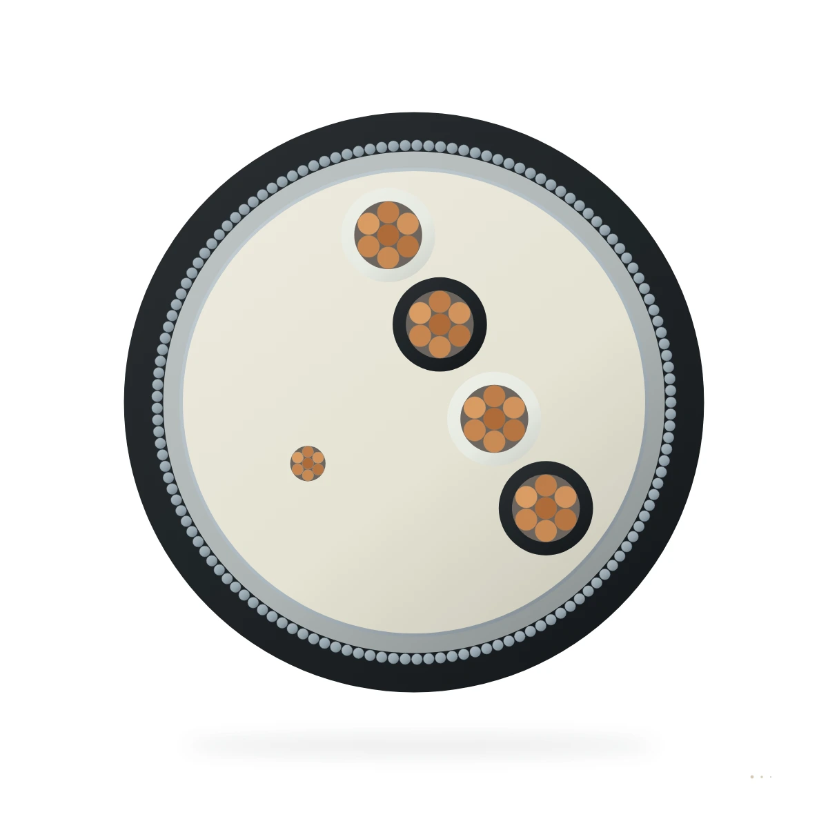
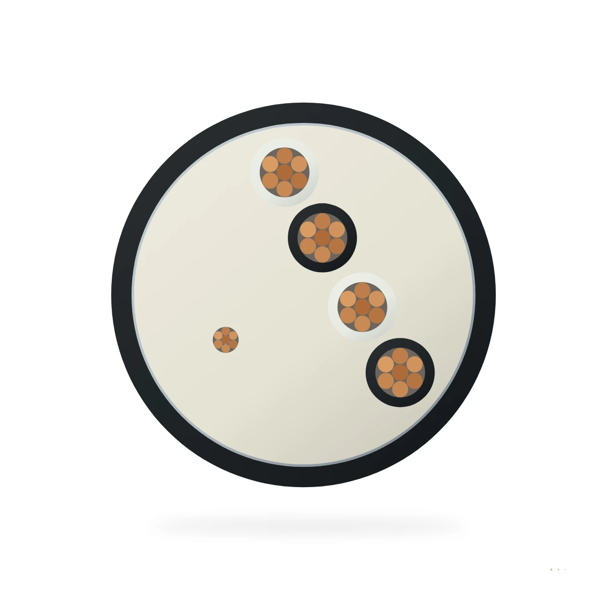
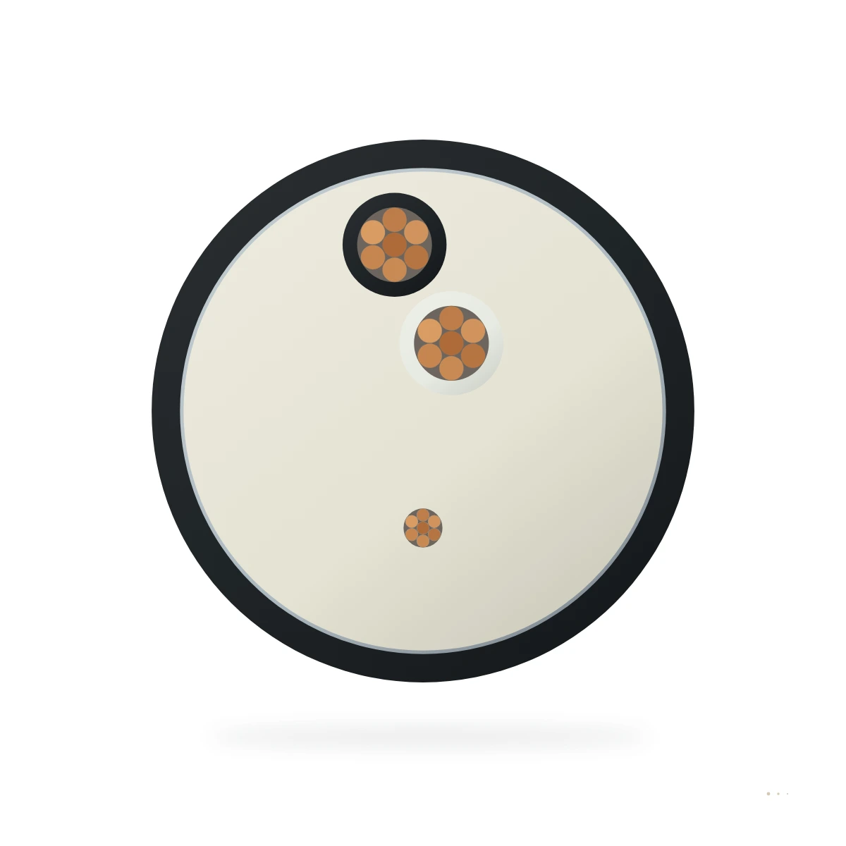
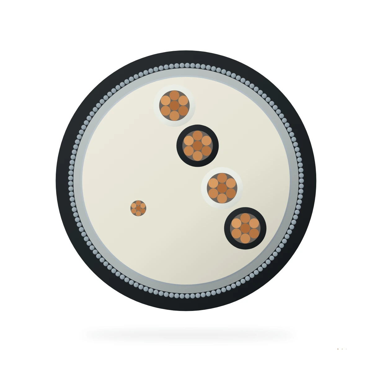
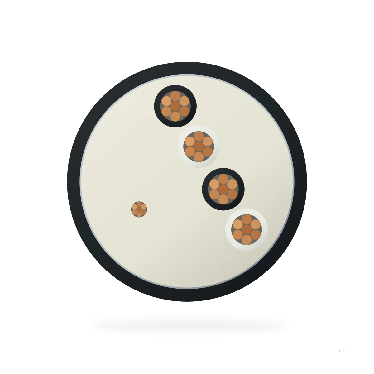
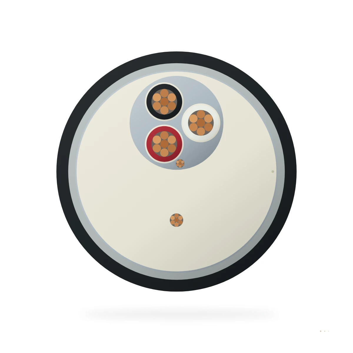
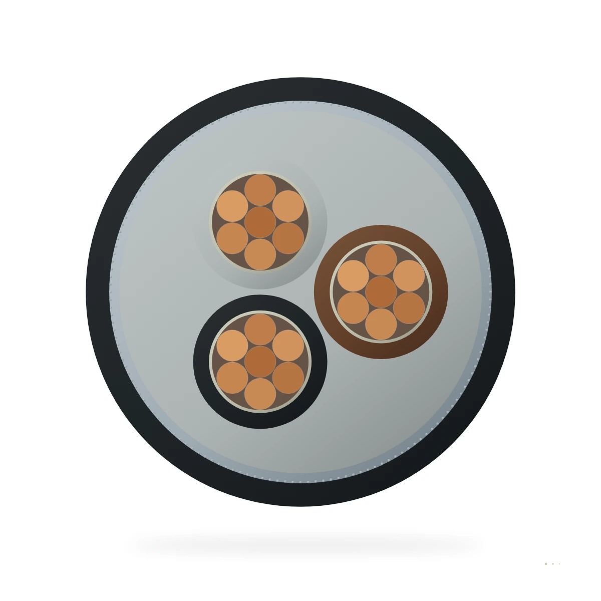
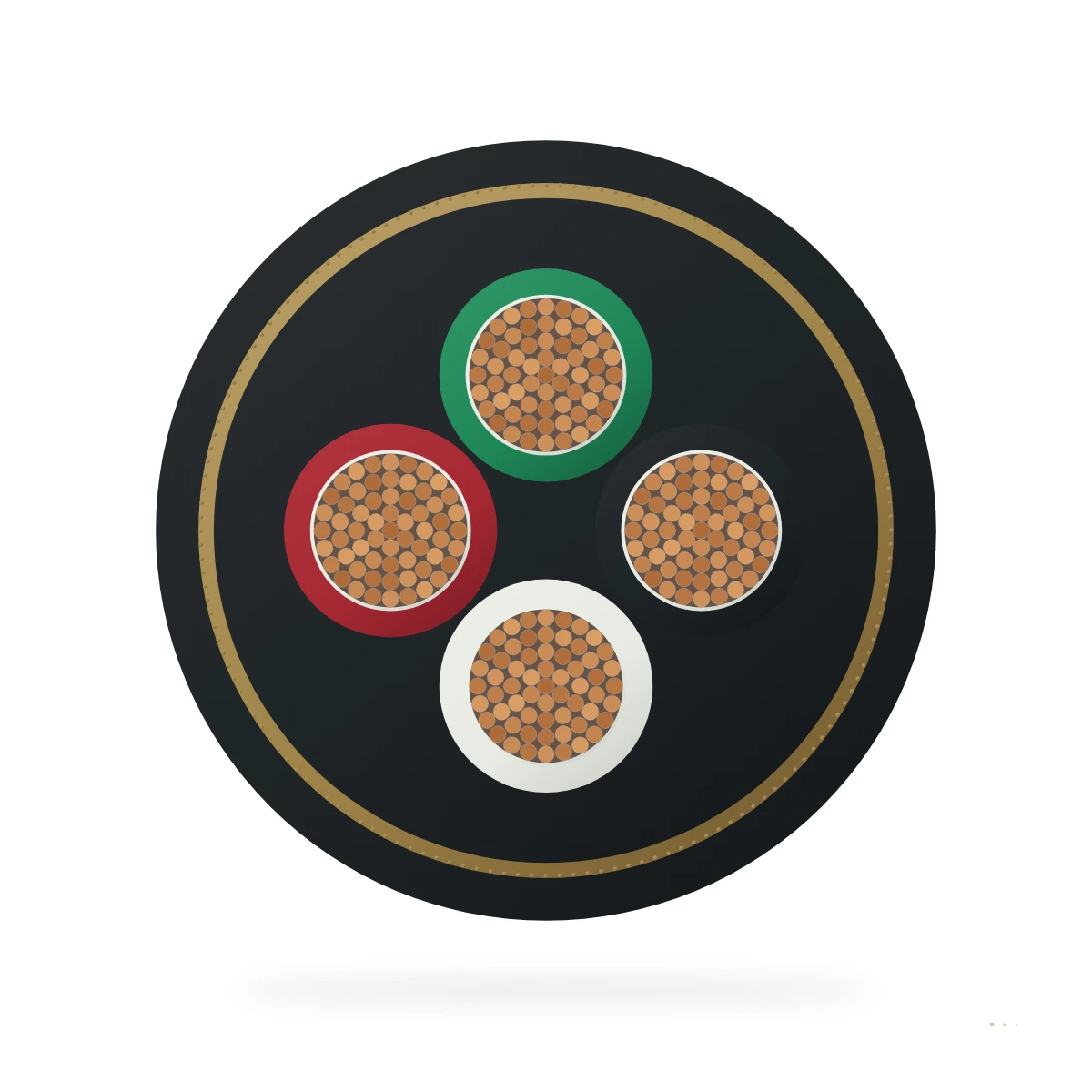
Offshore, shipboard and well logging
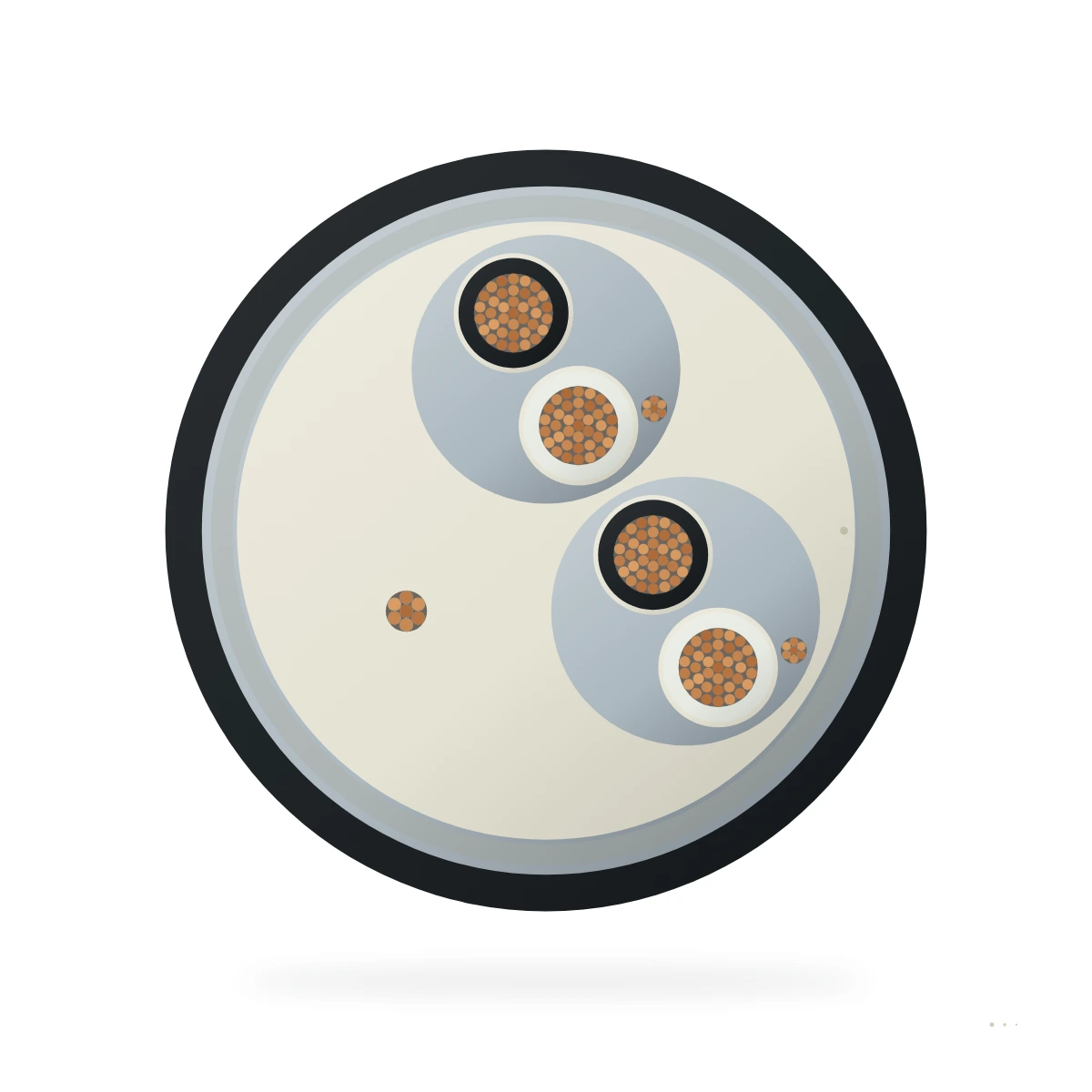
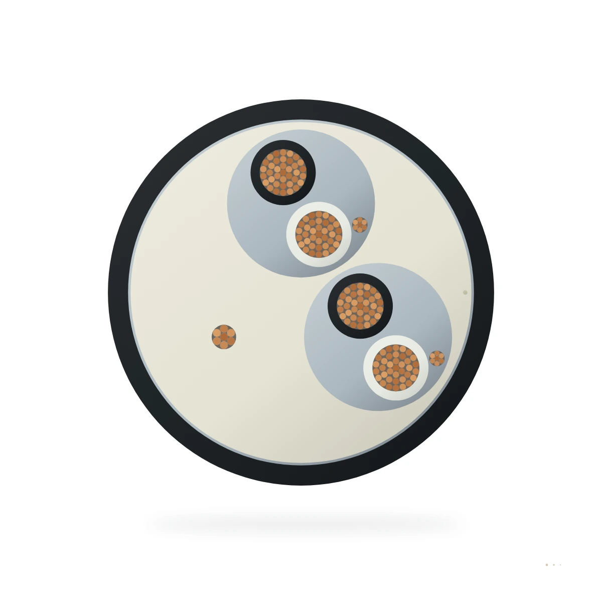
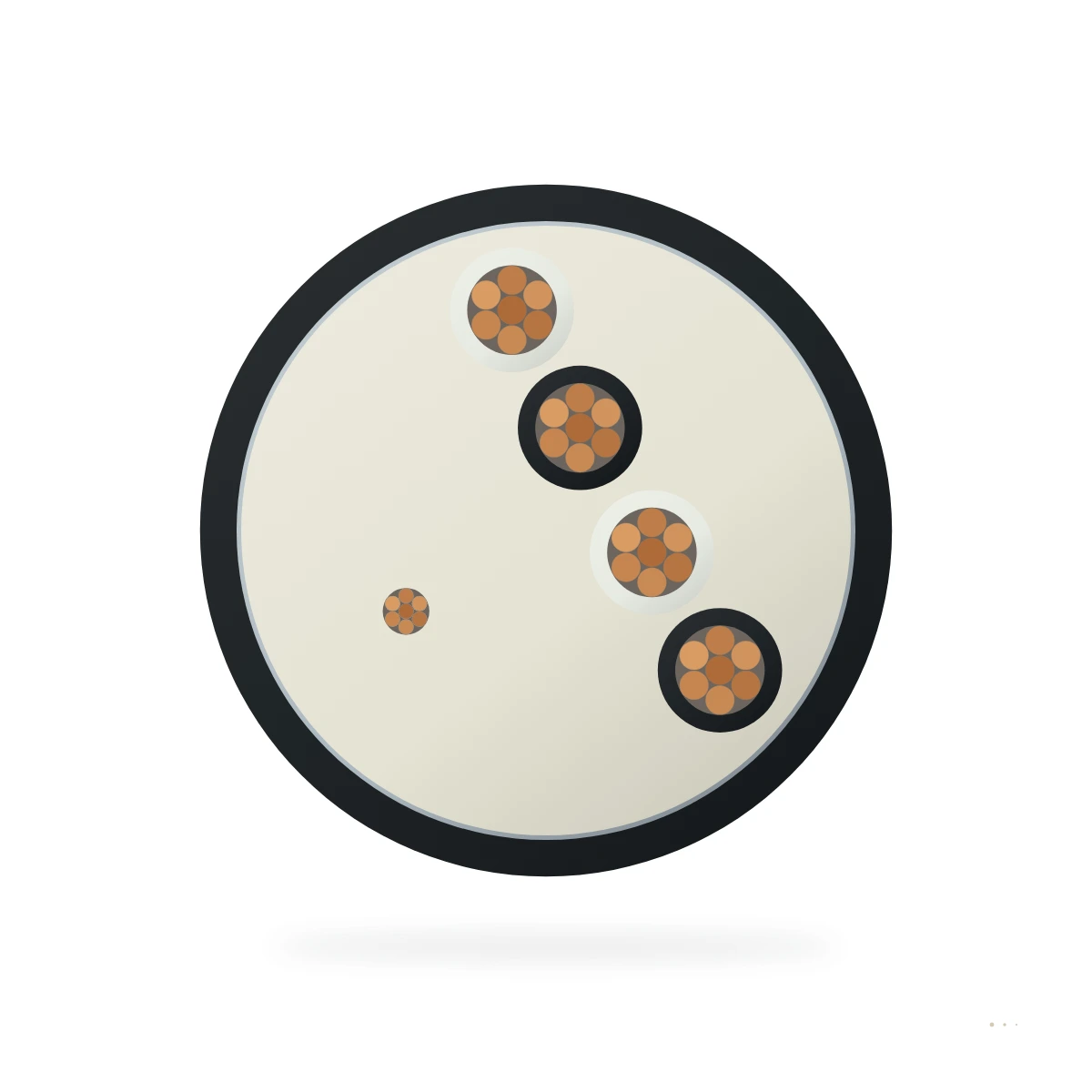
Offshore BS 6883/7917 and NEK 606 instrumentation, naval thermocouple and armoured wireline logging cables.
13 cables
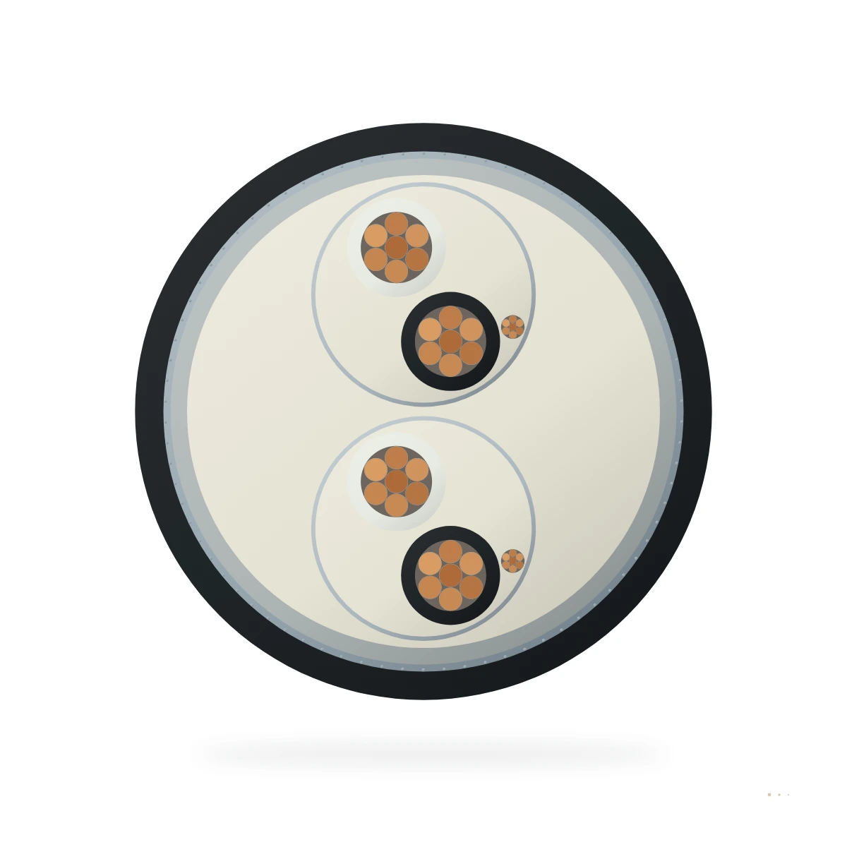
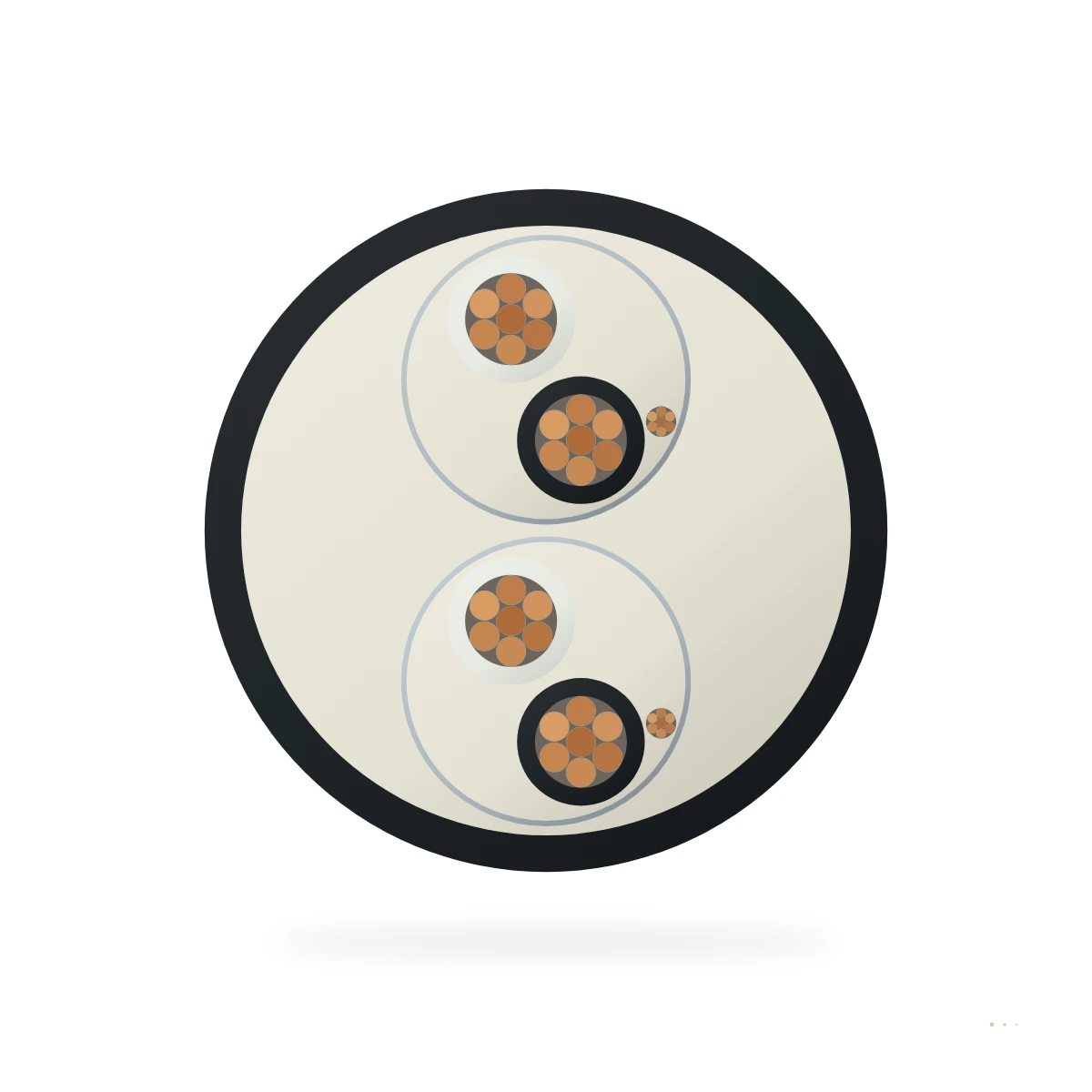
Thermocouple and RTD extension leads
IEC 60584 and ANSI MC96.1 thermocouple extension, compensating, mineral-insulated and RTD sensor cables.
12 cables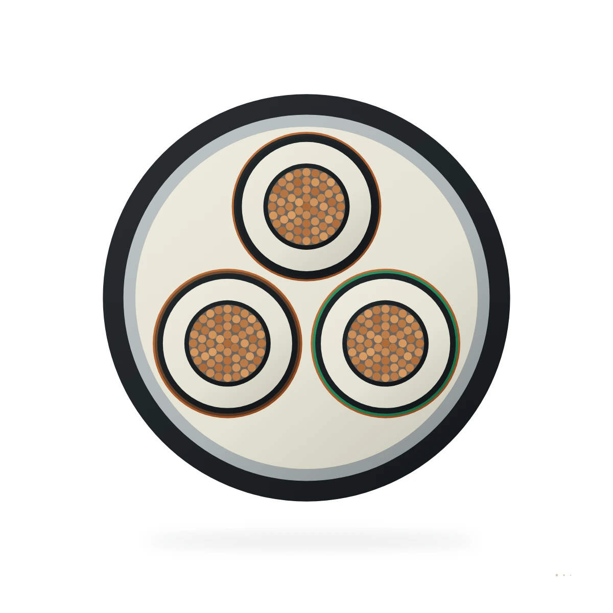


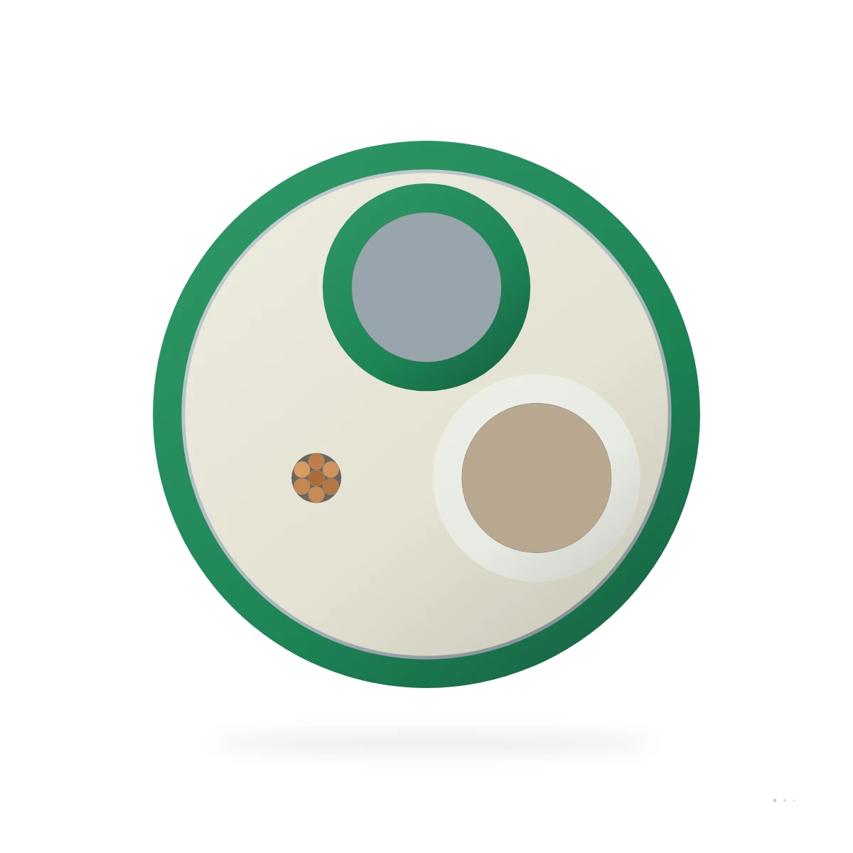



Nuclear, leak and cryogenic sensing
Nuclear Class 1E measuring cables, liquid-leak sensing cables, piezoelectric coax and cryogenic readout looms.
17 cables





Choosing instrumentation cables
Four things decide most selections. Our engineers check the rest against your application.
Application and movement duty
- Define whether the cable runs in a fixed tray, energy chain, festoon loop, reel or trailing route.
- Match travel speed, bend radius and tensile load to the mechanical construction.
- Select a support element or armour when the cable carries suspended weight or external crush loads.
Voltage class and core layout
- Match the rated voltage U0/U to the supply system and earthing arrangement.
- Specify phase cross-sections, protective earth, pilot cores or control pairs required by the machine.
- Include copper braid, tape or semiconductive screens where EMC or electric-field control is needed.
Operating environment and sheath
- Choose rubber, PUR, LSZH, PVC, fluoropolymer or silicone sheaths for the thermal and chemical exposure.
- Verify oil, UV, water immersion, cold-flex or circuit-integrity ratings against site conditions.
- Check outer diameter and gland compatibility at both terminations.
Standard and documentation
- Confirm the governing standard family required by the project specification.
- Verify conductor class, colour code or core numbering for the destination region.
- Include operating duty and cable length in your enquiry so we can confirm the build.
Questions buyers ask
Not covered here? Send your drawing and an engineer replies within 2 business hours.
Ask on WhatsAppHow do I select the right instrumentation cable from this range?
Start by filtering the list by movement duty, voltage band and sheath material. Compare how each instrumentation cable is constructed—conductor flexibility, insulation compound, screening and outer jacket—against your machine's bending radius, travel speed and ambient temperature. Open the product page or datasheet to check core counts, cross-sections and outer diameters before sending your enquiry.
When should instrumentation cables include metallic screening or armour?
Specify a copper braid or foil screen when instrumentation cables run near variable-frequency drives, carry analogue or fieldbus signals, or require medium-voltage electric-field control. Choose steel wire braid or armour when the installation faces rock fall, crushing loads or high pulling tension in roadways, decks or subsea routes.
Which outer sheath compound suits harsh industrial environments?
Heavy-duty rubber (PCP or CPE) provides balanced mechanical toughness, weather resistance and thermal stability. Polyurethane (PUR) resists cuts, abrasion and mineral oils on fast-moving chains, reels and trolleys. Halogen-free LSZH compounds reduce smoke and acid gas in tunnels, ships and enclosed buildings, while fluoropolymers and silicone handle extreme heat.
What details should I include in an RFQ for instrumentation cables?
Include the model designation or governing standard, rated voltage, number of cores and conductor cross-sections, along with the installation method, minimum bend radius, ambient temperature range and required delivery lengths. If you are replacing an existing cable on a machine, share the sheath marking so we can match the specification.
Engineering reference
Background on how instrumentation cables are built, rated and specified.
Read the full reference
Instrumentation cable carries low-level measurement, monitoring and process signals between field instruments, junction boxes, marshalling panels and control systems. Common circuits include transmitters, sensors, thermocouples, alarms and analogue or digital measurement loops. These signals can be more sensitive to noise and circuit-to-circuit coupling than ordinary discrete control wiring, so conductor arrangement, pair or triad lay-up, screening, capacitance, identification and installation practice all influence selection.
Typical users include EPC contractors, offshore module builders, shipyards, oil and gas operators, process plants, power projects and industrial control-system integrators. Their questions are usually commercial and technical at the same time: does the cable have the required pair or triad count, voltage, screen and armour; does it match the project standard and fire specification; and what documentation accompanies it? The application cannot be defined by the word "instrumentation" alone.
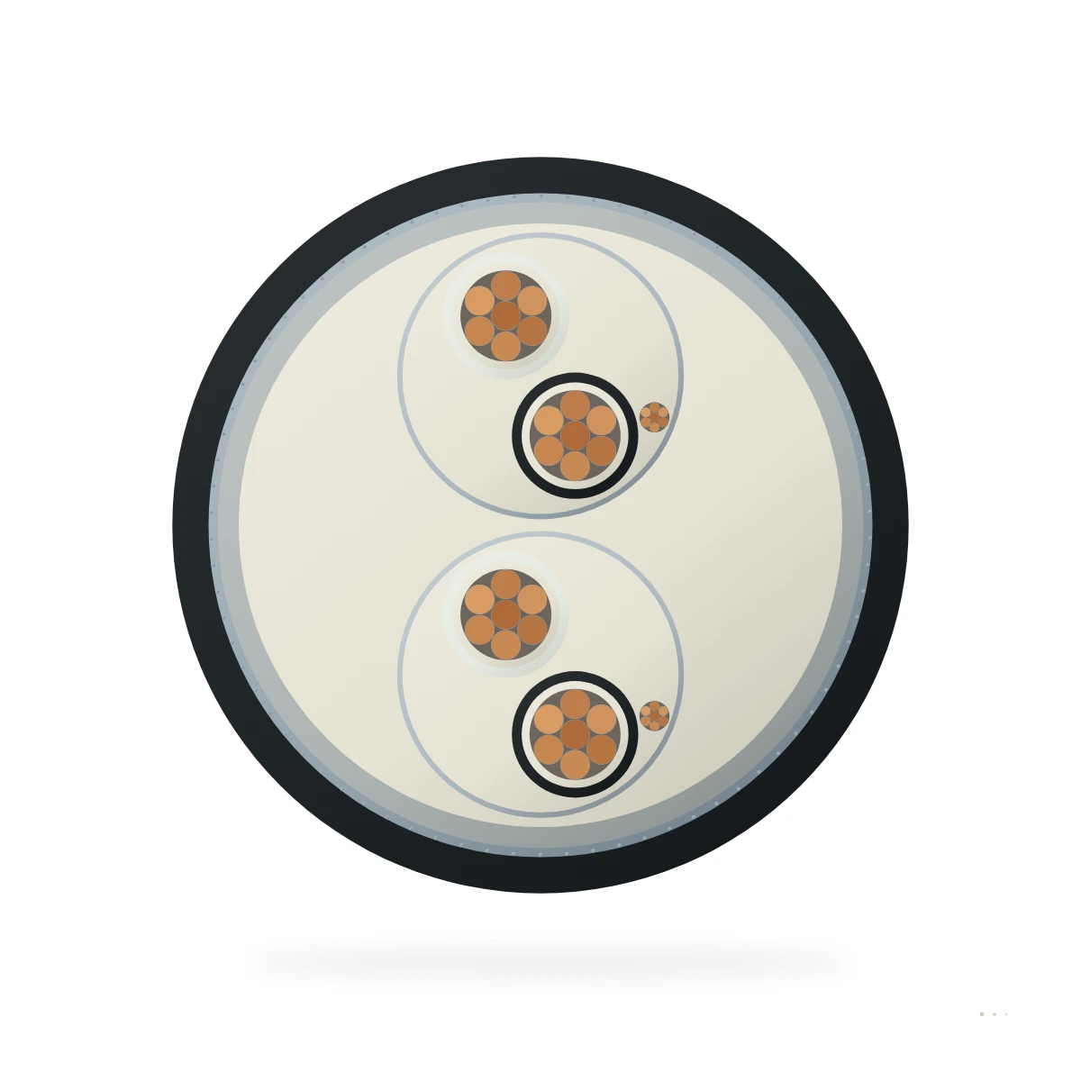
TEBAOFLEX's Instrumentation Cable range includes product families centred on marine and offshore fixed installations. IEEE 1580 Type P covers power, control, instrumentation and dedicated VFD constructions rated 2 kV or below, with screened pairs or triads available by model. NEK 606 BFOU/RFOU covers offshore power, control, instrumentation and communication constructions by model. Common BFOU/RFOU designs use tinned copper conductors, EPR insulation, halogen-free coverings, tinned-copper-wire braid armour or screen and an SHF2 outer sheath; instrumentation variants can use individual or collective screens. For procurement, narrow these broad families to the exact instrumentation designation before making a technical or compliance statement.
Start with the signal schedule. Specify whether each circuit is 4-20 mA, thermocouple, resistance-temperature detector, pulse, alarm, serial or another defined signal; then state the required number of pairs, triads or cores. Pair and triad constructions are not interchangeable. Conductor material, class and size affect resistance and termination, while twisting and circuit grouping affect noise rejection and crosstalk. For thermocouple circuits, the conductor or extension-cable material must match the measurement system; select that capability from the designated construction rather than from the generic instrumentation label.
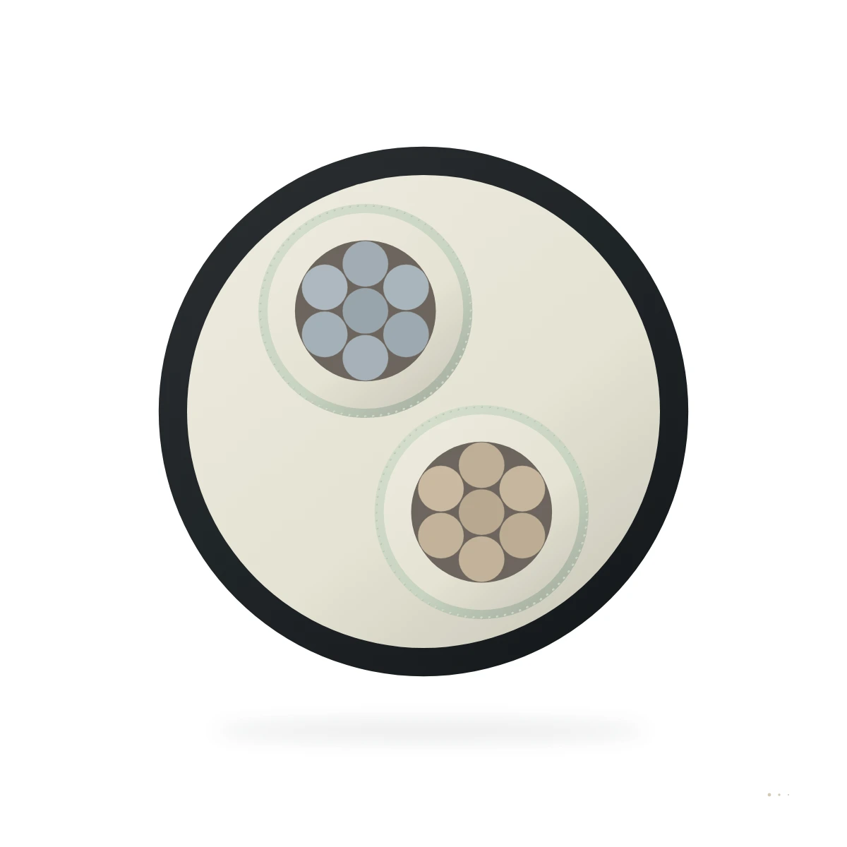
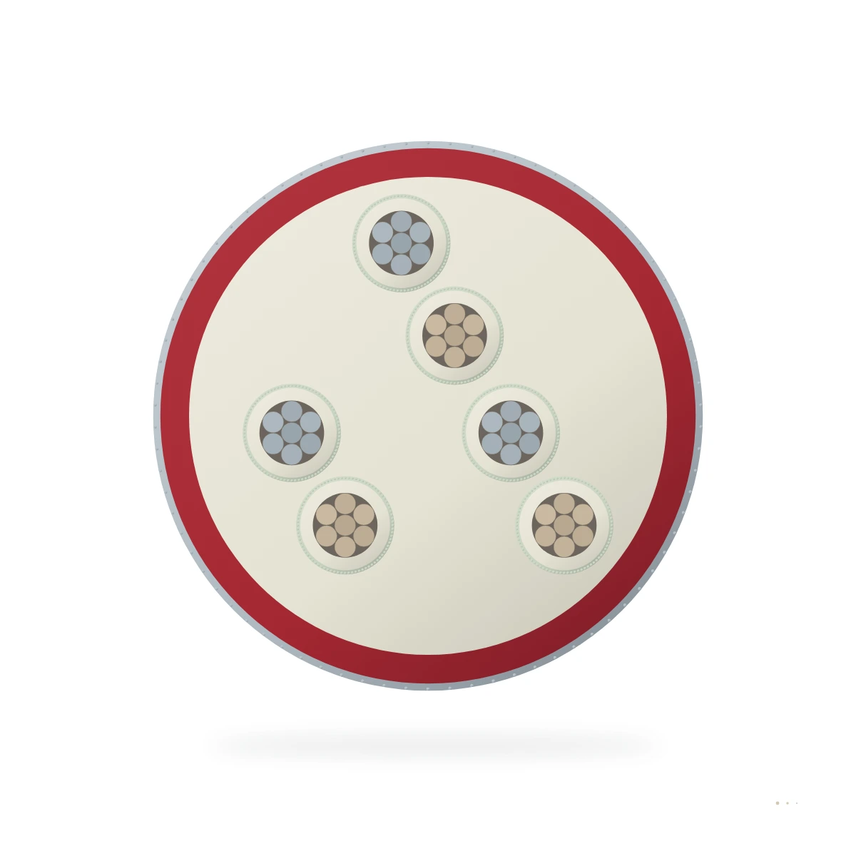
Screening should be chosen from the actual electromagnetic environment. An overall screen surrounds the complete cable core and can help address external interference. Individual screens around pairs or triads can improve separation between sensitive circuits; some projects require both individual and overall screening. The IEEE 1580 Type P and NEK 606 families include screened pair/triad variants, while individual and collective screening remains model-specific. State the required arrangement, drain or braid construction, screen continuity and termination method in the RFQ.
Cable screen performance depends on the installed system. Routing parallel to power cables, proximity to VFD output, tray separation, gland and armour bonding, panel earthing and screen termination can be as important as the cable construction. The project's control-system and grounding philosophy should determine whether and where instrumentation screens are bonded. Use the specified instrumentation-screen practice for a low-level loop, because VFD motor-cable and medium-voltage screen rules serve different functions.
Mechanical protection should match the route. In a fixed offshore installation, determine whether the cable runs in protected tray, open deck, conduit, equipment skid or an area exposed to impact. Armour or metallic braid may be required for mechanical protection and project practice, but its role should be distinguished from individual signal-pair screens. Provide pulling length, bend constraints, gland type and minimum installation temperature. The IEEE 1580 Type P and NEK 606 families are centred on fixed offshore work; use them in a continuous-flex or festoon route only where the selected construction's data covers that duty.
Environmental and fire requirements are often decisive offshore. Specify operating temperature, sunlight, oil, drilling mud, salt, water, chemical exposure, low-smoke and halogen limits, flame propagation and any circuit-integrity requirement. NEK 606 listings distinguish RFOU as a flame-retardant family and BFOU as adding a mica-based fire barrier for critical circuits. Where mud resistance is required, specify the M variant with its exact suffix, test scope and supporting data. IEEE Type P fire performance, armour, outer sheath and approvals likewise depend on the selected construction.
Standard references need exact editions and documentary expectations. IEEE 1580 and NEK 606 serve different marine/offshore specification frameworks. The NEK 606 listing references NEK TS 606:2025, while project documents may name another edition. State any vessel, flag, class or end-user approval requirement in the enquiry. Request approval or test evidence for the exact cable, size and construction; a standard-family reference alone is not third-party certification.
For an RFQ, provide the project and installation area, signal types, pair/triad/core count, conductor size, circuit voltage, individual and overall screen arrangement, drain/armour and grounding plan, insulation and sheath preference, fire and LSZH performance, environmental exposure, tray/conduit/gland details, required standard and edition, class or approval documents, circuit identification, total length, drum schedule and destination.
The IEEE 1580 Type P and NEK 606 BFOU/RFOU products below are configurable offshore cable families. Instrumentation suitability depends on selecting and documenting the exact screened pair, triad or multicore construction required by the project.