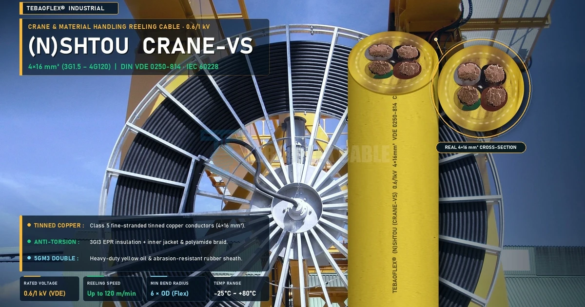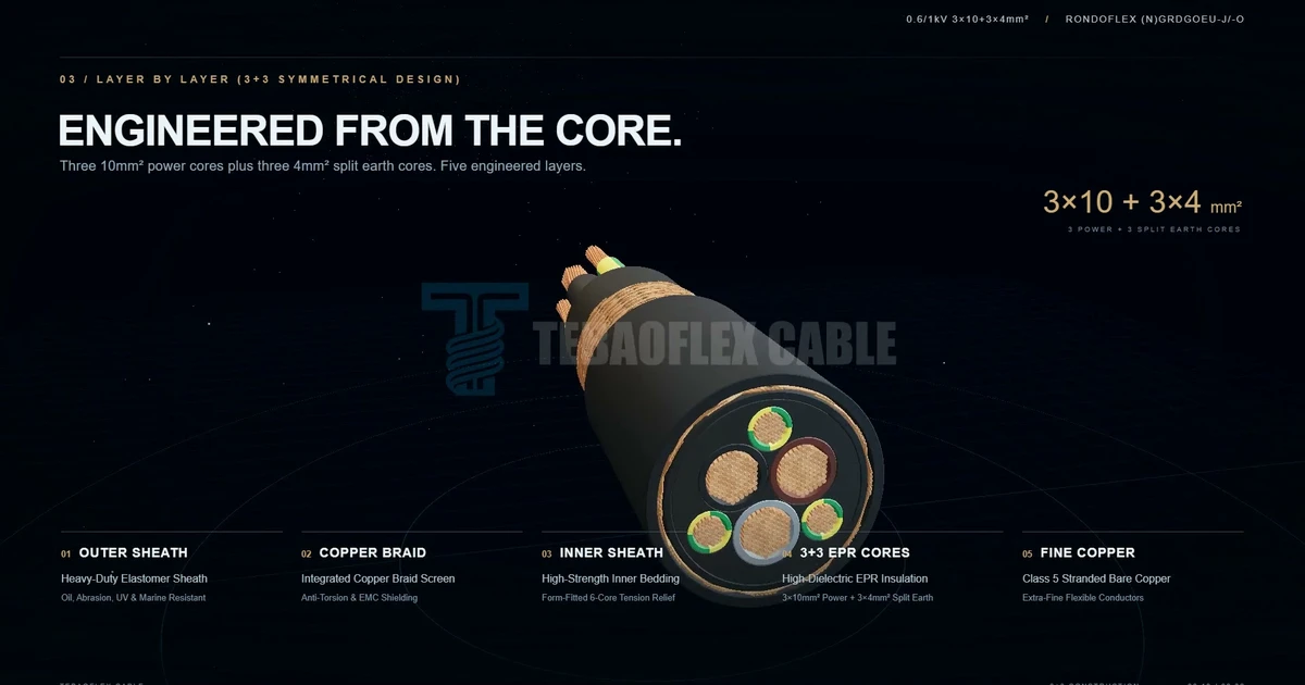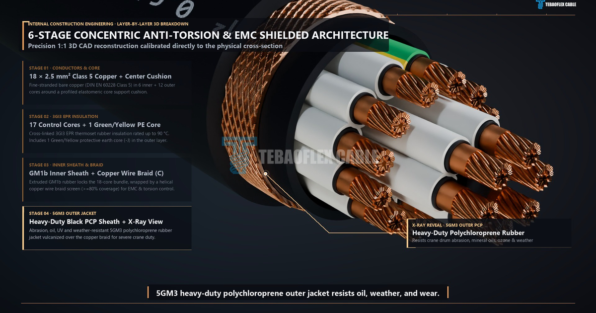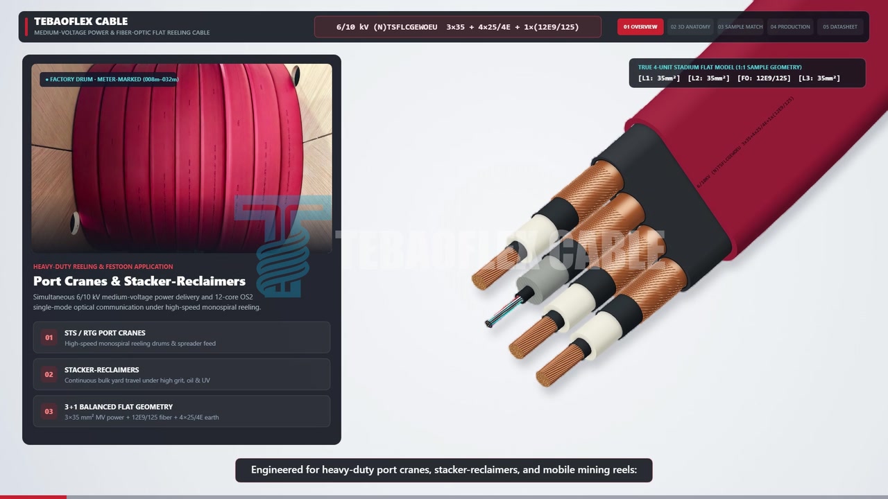
What the video shows
A 68-second walkthrough of the 6/10 kV hybrid power and fiber-optic crane reeling cable, combining schematic animations and sample footage.
The video illustrates a sample, process, or operating context. Final product construction, suitability, standards, and test acceptance criteria are confirmed against the ordered specification.
By TEBAOFLEX Jyen. Updated on October 23, 2026.
Media delivery note: this page presents a 1080p/60fps video and 1280×720 frame images. References to 4K footage and 4000×3000 photographs describe the source material, not the resolution of the web files.
TL;DR: This 68-second (1:08) video presents our 6/10 kV TEBAOFLEX (N)TSCGEWOEU+FO 3x70+2x35/2+12FO (62.5/125) hybrid power and fiber-optic reeling cable built to DIN VDE 0250-813 (2026). It pairs schematic 3D monospiral crane reel and 6-layer cutaway animations (0:03 to 0:54) with real 4K 60fps sample video and 4000x3000 macro photos (0:00 to 0:03and0:54 to 1:02). Three70 mm²Class 5 copper phase cores (IEC 60228, 2026), triple-extruded3GI3EPR (17 kV AC test), two35/2 mm²split earth cores, and a 12FO (62.5/125 µm) fiber unit sit inside an EPR inner bedding. A vulcanized anti-torsion braid (±100 °/m, 20 to 25 N/mm² pull) and a blackCR / 5GM5jacket (49.2 mm nominal OD) support 120 m/min crane reeling.
On automated ship-to-shore (STS) cranes, rail-mounted gantry (RMG) cranes, and stacker-reclaimers, medium-voltage cables must carry both 6/10 kV motor power and EMI-free optical data in one round profile. They must also survive 120 m/min travel speeds and high tension on giant monospiral reels. This video page examines our 6/10 kV (N)TSCGEWOEU+FO 3x70+2x35/2+12FO cable in a 68-second walkthrough. It covers the 6-layer strip-back and real sample clips (2026 embossed sheath mark). Below, you can watch the full video, check the scene log, review DIN VDE 0298-4 ampacity tables, and use our selection checklist. This page was reviewed by the TEBAOFLEX editorial engineering board.
What Happens in Each Scene of the 68-Second Product Video?
The 68-second video combines two visual formats so crane engineers can verify both monospiral reeling motion and real build quality. First, it shows real sample 4K 60fps video and 4000x3000 macro photos (0:00 to 0:03 and 0:54 to 1:02). Second, it shows schematic 3D monospiral crane reel and 6-layer CAD cutaway animations (0:03 to 0:54 and 1:02 to 1:08). The table below logs every scene by timestamp.
Timestamp
0:00 - 0:03
- Video Scene & Visual Mode: Opening Cover Card (Real sample + reel).
- Key Technical Details Shown on Screen: Shows a real black sample printed
TEBAOFLEX (N)TSCGEWOEU + FO 6/10kV 3x70+2x35/2+12FO(62.5/125) 2026and a real cut face.
0:03 - 0:08
- Video Scene & Visual Mode: 01 / Cross-Section Reveal (Schematic 2D/3D).
- Key Technical Details Shown on Screen: Reveals the
3x70 + 2x35/2 + 12FOlayout with3GI3EPR, split earth cores,12FOunit, inner bedding, braid, and blackCRsheath.
0:08 - 0:11
- Video Scene & Visual Mode: 02 / Application Scene: Step 01 (Schematic 3D).
- Key Technical Details Shown on Screen: Shows
Heavy Rail Machinery & Giant Monospiral Cable Reelfor high-speed port, mining, and bulk-handling cranes.
0:11 - 0:15
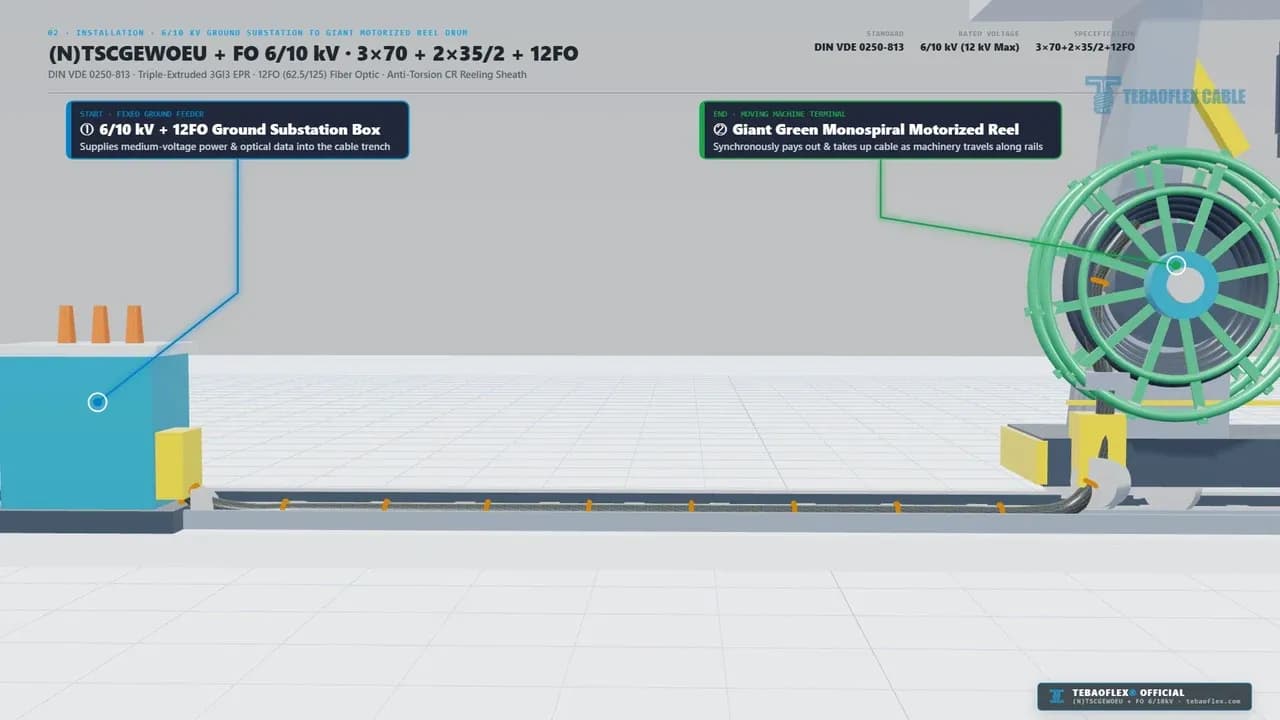
- Video Scene & Visual Mode: 02 / Substation to Reel: Step 02 (Schematic 3D).
- Key Technical Details Shown on Screen: Labels
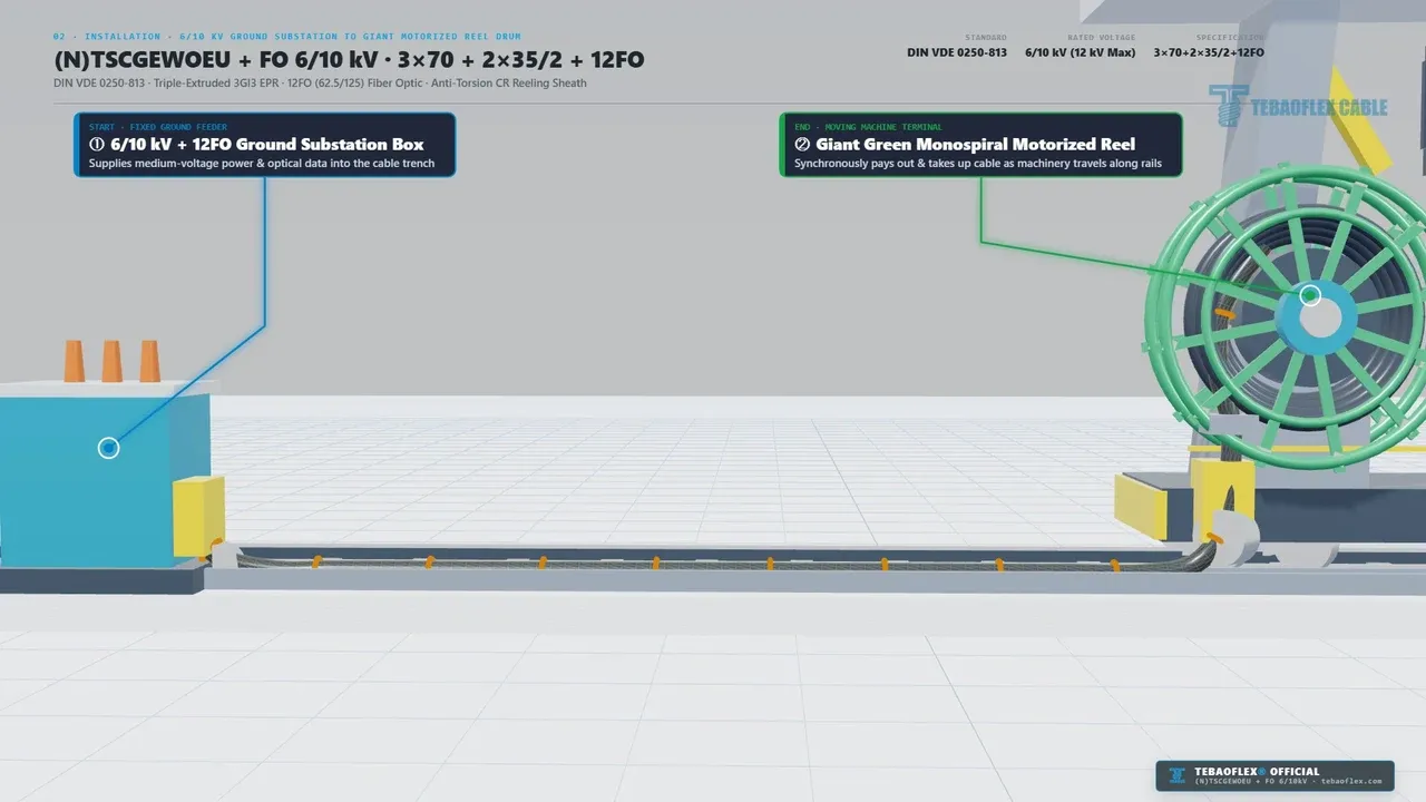
1. 6/10 kV + 12FO Ground Substation Boxand2. Giant Green Monospiral Motorized Reelalong the rail trench.
0:15 - 0:18
- Video Scene & Visual Mode: 02 / Power + 12FO Telemetry: Step 03 (Schematic 3D).
- Key Technical Details Shown on Screen: Highlights
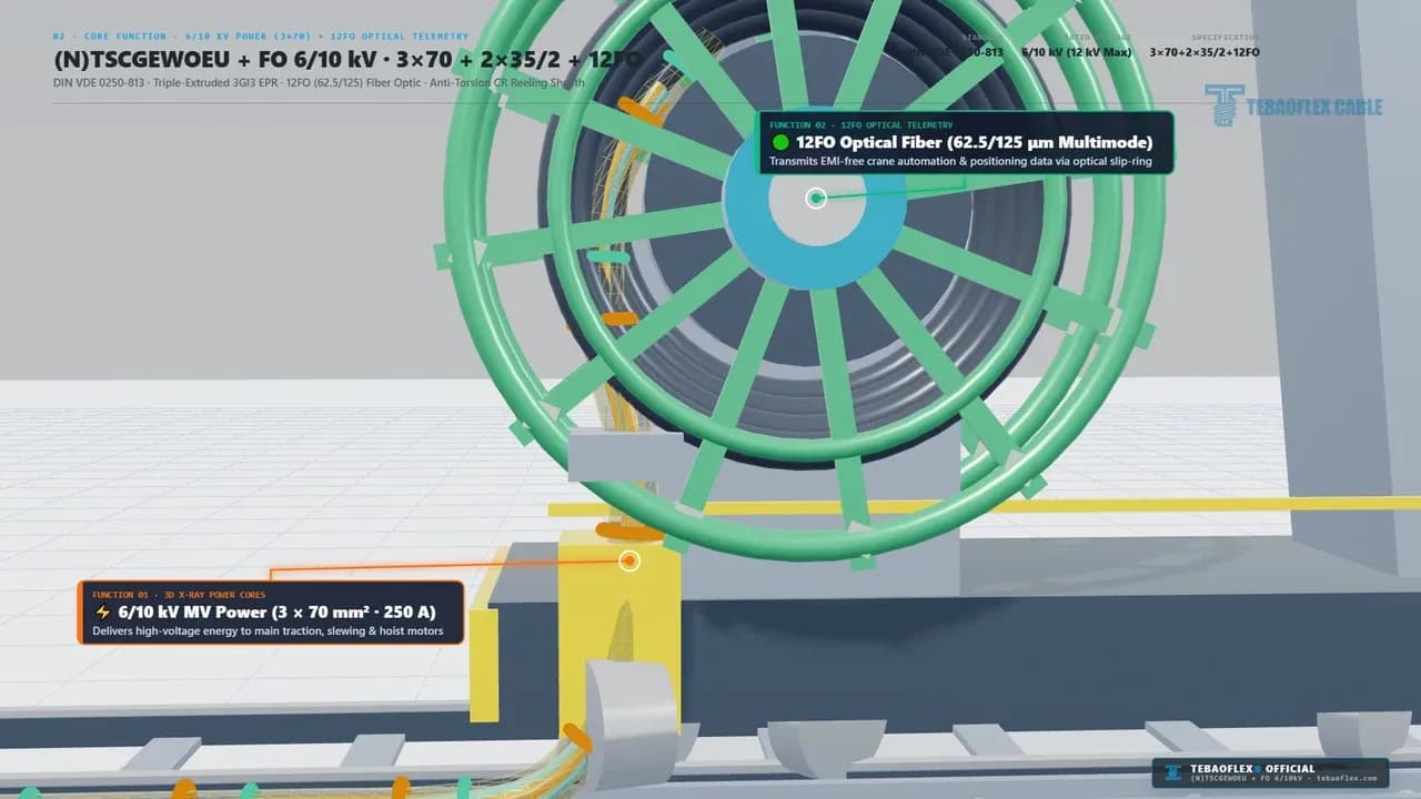
6/10 kV MV Power (3 x 70 mm² · 250 A)and12FO Optical Fiber (62.5/125 µm Multimode)via optical slip-ring.
0:18 - 0:21
- Video Scene & Visual Mode: 02 / Fairlead & Anti-Torsion: Step 04 (Schematic 3D).
- Key Technical Details Shown on Screen: Zooms into
±100 °/m Anti-Torsion Braid & 4-Roller Fairleadunder120 m/minhigh-tension reeling.
0:21 - 0:39
- Video Scene & Visual Mode: 03 / 6-Layer Strip-Back (06 to 01) (3D CAD cutaway).
- Key Technical Details Shown on Screen: Strips back
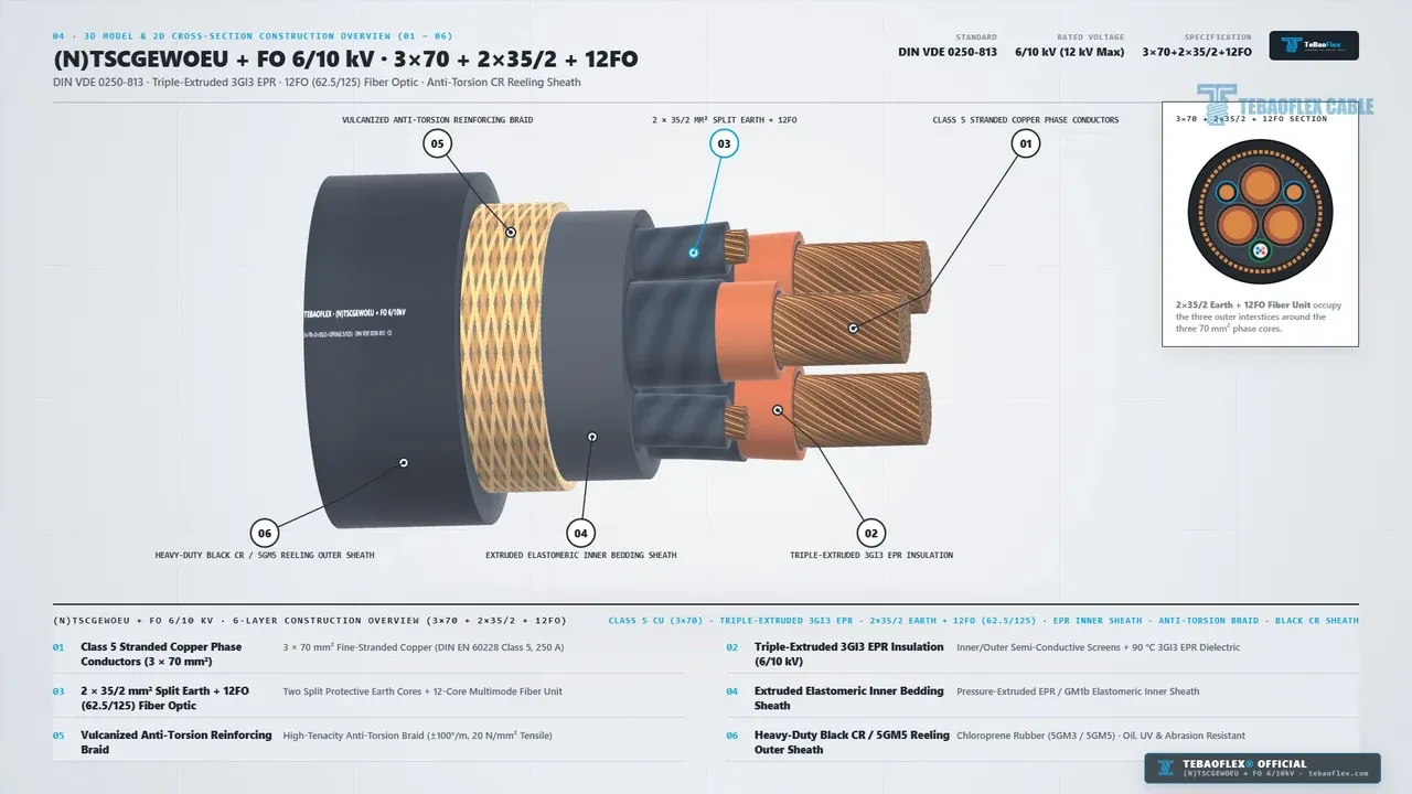
06 Black CR Sheath,05 Anti-Torsion Braid,04 EPR Inner Bedding,03 2x35/2 + 12FO,02 3GI3 EPR, and01 Class 5 Cu.
0:39 - 0:48
- Video Scene & Visual Mode: 04 / 3D & 2D Construction Summary (Schematic 3D/2D).
- Key Technical Details Shown on Screen: Combines all 6 layer callouts (
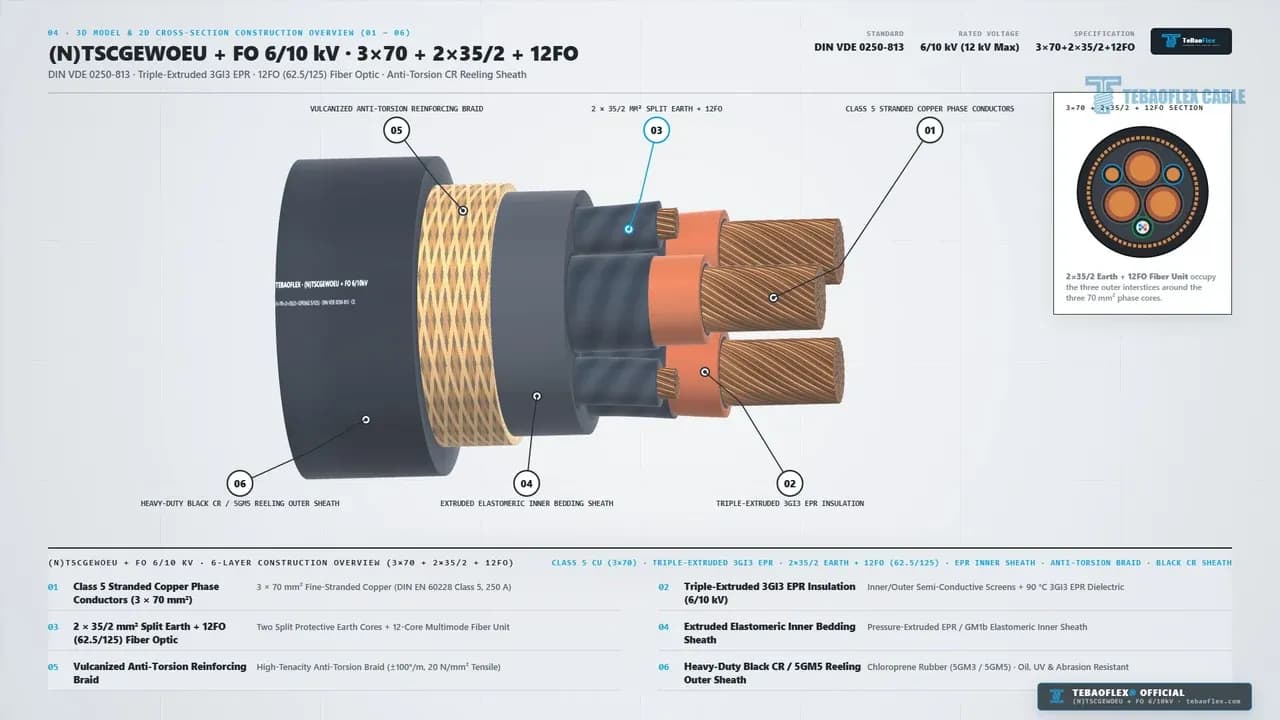
01 to 06), a3x70 + 2x35/2 + 12FO SECTIONinset, and a 6-row table.
0:48 - 0:54
- Video Scene & Visual Mode: 05 / Key Technical Specifications (Engineering card).
- Key Technical Details Shown on Screen: Lists
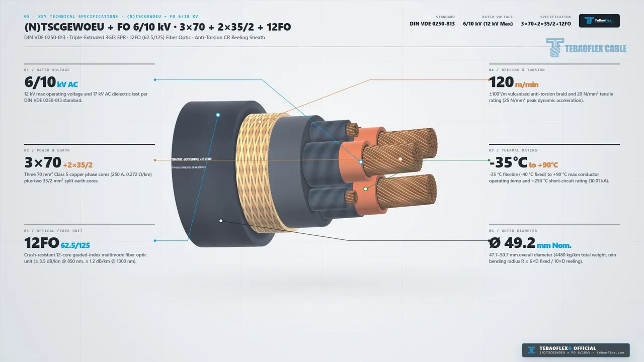
6/10 kV AC(17 kVtest),3x70+2x35/2,12FO 62.5/125,120 m/min(±100 °/m,20-25 N/mm²),-35 to +90 °C, and49.2 mm OD.
0:54 - 0:57
- Video Scene & Visual Mode: 06 / Real Sample End-Face (01 of 03) (Real 4K 60fps).
- Key Technical Details Shown on Screen: Inspects the real
3x70+2x35/2+12FOsample cut, showing three70 mm²phase cores, two35/2 mm²earth cores, and the12FOunit.
0:57 - 0:59
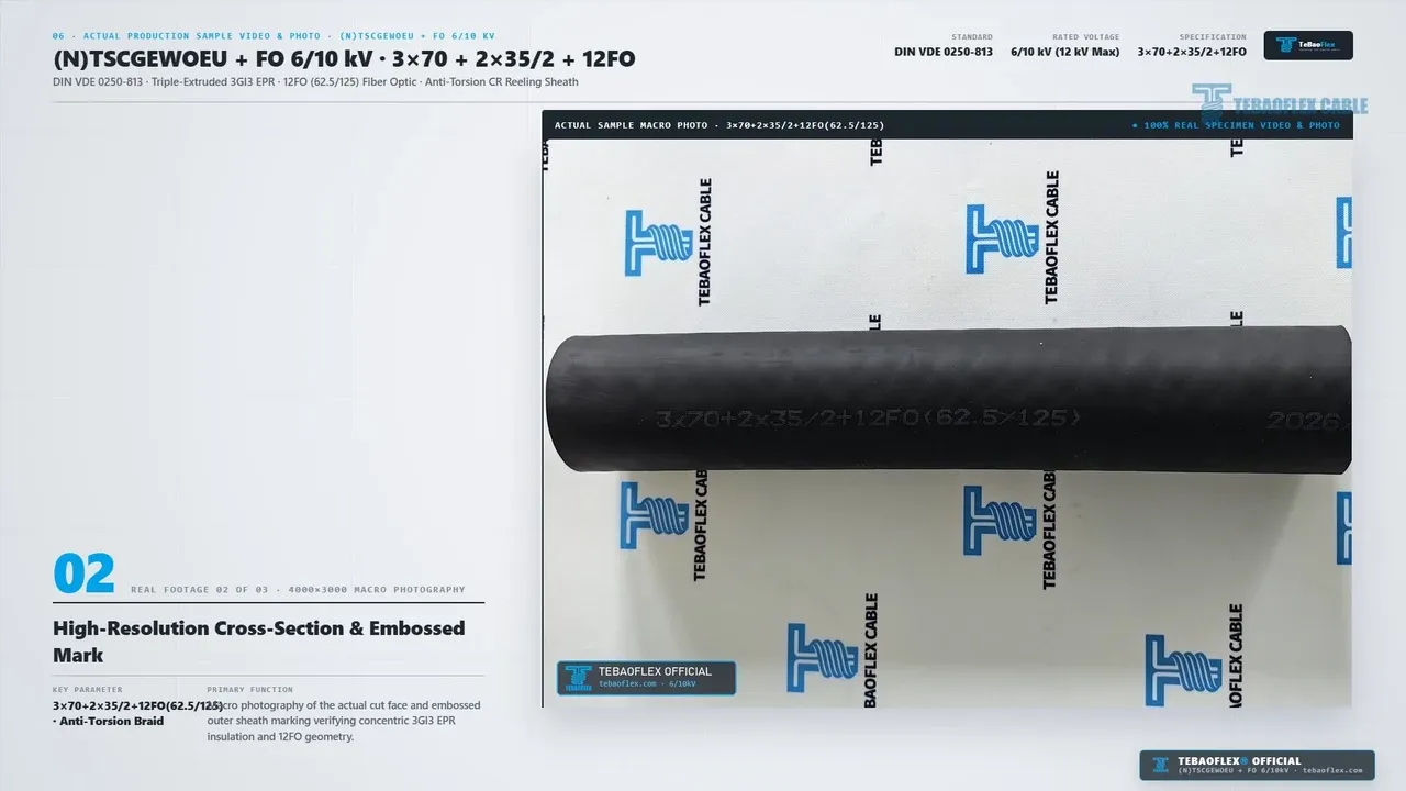
- Video Scene & Visual Mode: 06 / Macro Cut & Embossed Mark (02 of 03) (4000x3000 photo).
- Key Technical Details Shown on Screen: Shows the
4000x3000macro cross-section (0:58) and the embossed outer sheath mark3x70+2x35/2+12FO(62.5/125) ... 2026(0:59).
0:59 - 1:02
- Video Scene & Visual Mode: 06 / Factory Sheath & Drum (03 of 03) (Real 4K 60fps).
- Key Technical Details Shown on Screen: Shows factory inspection of the
49.2 mmblackCRjacket in the cooling trough (1:00) and haul-off guide wheel (1:01).
1:02 - 1:08
- Video Scene & Visual Mode: Closing Brand Card (Graphic summary card).
- Key Technical Details Shown on Screen: Displays
Jiangsu Tebaoflex Special Cable Co., Ltd.(Publisher: TeBaoFlex Jyen,tebaoflex.com,info@tebaoflex.com,+86 185 9591 3361).
Video Scope Note: The ground substation box, rail trench, giant green monospiral reel, 4-roller fairlead, and 6-layer strip-back animations (0:03 to 0:54) are schematic engineering views. They are not terminal footage and are not to scale. Real physical sample 4K 60fps video,4000x3000macro photos, and factory extrusion line clips appear at0:00 to 0:03and0:54 to 1:02. No live high-voltage test bays appear in this clip. All electrical, optical, and mechanical values represent official ratings under DIN VDE 0250-813, IEC 60228, and DIN VDE 0298-4.
Video at a Glance: Video & Sample Technical Summary
The table below lists the verified specifications shown in the video and defined by DIN VDE 0250-813 (2026).
Parameter
Commercial Model Designation.
- Verified Video & Standard Specification:
TEBAOFLEX (N)TSCGEWOEU + FO 6/10 kV 3x70 + 2x35/2 + 12FO (62.5/125).
Reference Standards.
- Verified Video & Standard Specification: DIN VDE 0250-813, DIN EN 60228 / IEC 60228 Class 5, DIN EN 50363-2-1.
Rated & Test Voltage.
- Verified Video & Standard Specification:
U0/U = 6/10 kV AC(maxUm = 12 kV AC); routine 5-min AC test 17 kV AC.
Power & Split Earth Cores.
- Verified Video & Standard Specification: 3 x 70 mm² Class 5 copper phase cores (
11.8 mmdia.,250 A,0.272 Ω/km,10.01 kASC) + 2 x 35/2 mm² split earth cores.
Optical Fiber Unit (12FO).
- Verified Video & Standard Specification: Crush-resistant 12-core 62.5/125 µm graded-index multimode fiber unit (
max 3.5 dB/km @ 850 nm,max 1.2 dB/km @ 1300 nm).
MV Insulation & Field Control.
- Verified Video & Standard Specification: Triple-extruded inner semi-con screen + 3GI3 EPR dielectric (
+90 °C) + outer semi-con screen.
Inner Bedding & Anti-Torsion.
- Verified Video & Standard Specification: Pressure-extruded
EPR / GM1binner sheath + vulcanized anti-torsion braid (±100 °/m, 20 N/mm² nominal / 25 N/mm² peak).
Reeling Outer Sheath.
- Verified Video & Standard Specification: Heavy-duty black Chloroprene Rubber (
CR / PCP,5GM3 / 5GM5) for oil, UV, ozone, and abrasion resistance.
OD, Weight, Speed & Bending.
- Verified Video & Standard Specification: 49.2 mm nominal OD (
47.7 to 50.7 mm); 4,480 kg/km mass; 120 m/min speed; min bend6 x Dfixed /10 x D(492 mm) reeling.
How Does the Video Illustrate Giant Monospiral Crane Reeling & 12FO Telemetry?
An (N)TSCGEWOEU+FO 6/10 kV cable is a hybrid medium-voltage rubber reeling cable built to DIN VDE 0250-813 for crane and mining reels. It houses three 3GI3 EPR phase cores, two split earth cores, and a 12-core fiber unit inside an anti-torsion double jacket.
In Section 02 (0:08 to 0:21), a four-step 3D view shows how our 3x70+2x35/2+12FO cable links a ground substation to a rail crane reel.
- Heavy Rail Machinery & Giant Monospiral Reel (
0:08 to 0:11). First, the clip shows a rail crane carrying a large single-spiral (monospiral) reel for high-speed port, mining, and bulk travel. - Ground Substation Box to Moving Machine Reel (
0:11 to 0:15). Second, as shown above, the cable feeds from1. 6/10 kV + 12FO Ground Substation Boxinto the rail cable trench. The moving end winds onto2. Giant Green Monospiral Motorized Reel. - Simultaneous 6/10 kV Power & 12FO Optical Telemetry (
0:15 to 0:18). Third, as shown below, the three70 mm²cores feed6/10 kV(250 A) power to drive and hoist motors. At the same time, the12FO (62.5/125 µm)unit sends EMI-free control and position data through the reel's optical slip-ring.
- 4-Roller Fairlead & ±100 °/m Anti-Torsion Protection (
0:18 to 0:21). Finally, as shown below, the cable passes through a 4-roller guide fairlead (min bend R = 10 x D = 492 mm). The vulcanized braid stops core twisting (±100 °/m) and jacket wear at 120 m/min.
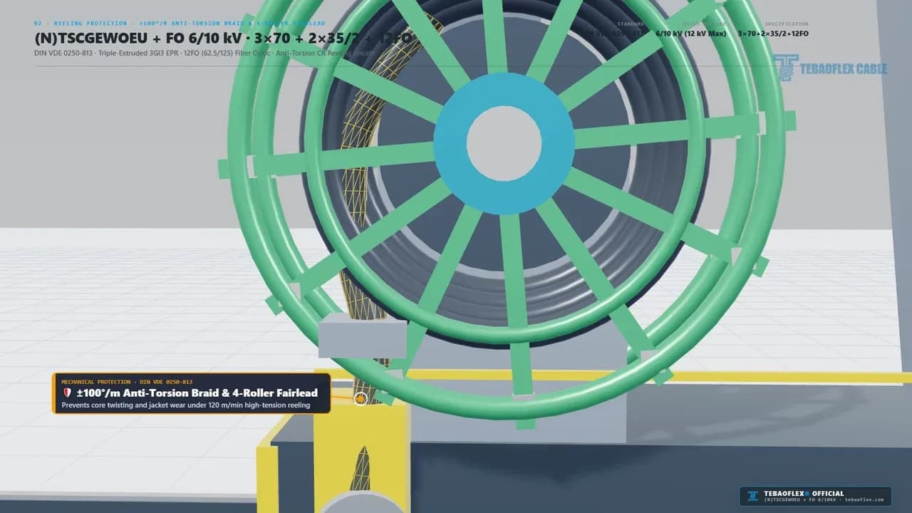
A monospiral crane cable reel is a narrow, large-diameter motorized drum that winds the cable in a single radial spiral (one cable width wide). It enables 120 m/min travel speeds and faster cooling than multi-layer cylindrical drums.
For example, when an STS container crane accelerates along the quay at 120 m/min, the fairlead applies both bending and axial pull (20 N/mm² continuous, 25 N/mm² peak). Without an anti-torsion braid locked between inner and outer sheaths, the outer jacket creeps and corkscrews, snapping the internal optical fibers. To explore related crane and mining cables, see our reeling cable product hub, our port and material handling crane guide, and our mining and tunneling cable solutions.
How Does the 6-Layer DIN VDE 0250-813 Construction Protect the 12FO Fiber Unit?
In Section 03 (0:21 to 0:39) and Section 04 (0:39 to 0:48), the video strips the (N)TSCGEWOEU+FO 6/10 kV 3x70+2x35/2+12FO cable from its outer jacket (Layer 06) down to its 70 mm² copper conductors (Layer 01).
DIN VDE 0250-813 is the German VDE standard governing medium-voltage (6/10 kV to 18/30 kV) EPR-insulated flexible trailing and reeling cables, including hybrid +FO constructions with integrated optical fibers (VDE Verlag, 2026).
You can browse related German medium-voltage rubber cable types in our VDE / DIN cable standards catalog.
Layer 06 & Layer 05: Heavy-Duty Black CR / 5GM5 Outer Sheath & Anti-Torsion Braid (0:21 to 0:27)
The outer jacket (Layer 06) uses heavy-duty black Chloroprene Rubber (CR / PCP, compound 5GM3 / 5GM5) per DIN VDE 0207-21 and DIN EN 50363-2-1. At 49.2 mm nominal outer diameter, it resists severe fairlead roller wear, oil (IEC 60811-404), UV sunlight, ozone, and -35 °C to +90 °C thermal cycling.
Beneath Layer 06 sits Layer 05, a vulcanized high-tenacity aramid/polyester anti-torsion reinforcing braid. It locks the outer and inner sheaths together to prevent corkscrewing under ±100 °/m torsion and 20 N/mm² (25 N/mm² peak) dynamic reeling pull (DIN VDE 0250-813, 2026).
Layer 04 & Layer 03: Extruded EPR Inner Bedding, 2 x 35/2 mm² Split Earth & 12FO Fiber Unit (0:27 to 0:33)
Under the anti-torsion braid, we extrude Layer 04, a pressure-vulcanized elastomeric EPR / GM1b inner bedding sheath. It fills the interstitial spaces and locks the six internal elements into a circular, anti-buckling core assembly.
A 3+3 interstitial hybrid core geometry is a balanced six-element cable layout where three medium-voltage phase cores form the main triangle. Two split earth cores (2 x 35/2 mm²) and one optical fiber unit (12FO) occupy the three outer valleys.
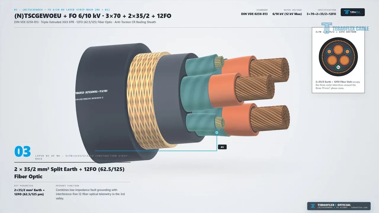
As shown at 0:31 above (Layer 03), the two 35/2 mm² (35 mm² total) split earth cores sit in two outer valleys. The crush-resistant 12FO (62.5/125 µm) multimode fiber unit sits in the third valley. This layout keeps the outer diameter compact (49.2 mm) and shields the optical fibers from radial drum pinch forces.
Layer 02 & Layer 01: Triple-Extruded 3GI3 EPR Insulation & 3 x 70 mm² Class 5 Copper (0:33 to 0:39)
Each phase core (Layer 02) is insulated with triple-extruded 3GI3 EPR (+90 °C operating, +250 °C short-circuit per DIN VDE 0207-20) sandwiched between inner and outer semi-conductive field control screens. Every finished core undergoes a 17 kV AC routine dielectric test.
At the center (Layer 01) sits a 70 mm² Class 5 fine-stranded copper phase conductor (11.8 mm diameter) per DIN EN 60228 / IEC 60228 (2026). It delivers 250 A per phase (0.272 Ω/km max DC resistance at 20 °C) and a 10.01 kA 1-second short-circuit rating (70 mm² x 143 A/mm² = 10.01 kA).
Layer No.
Layer 01.
- Structural Component: Phase Cores (
3 x 70 mm²). - Compound / Standard Code: Class 5 copper (
11.8 mmdia., IEC 60228). - Primary Mechanical, Electrical & Optical Function: Delivers 250 A (
0.272 Ω/km, 10.01 kA SC) with high flexing life.
Layer 02.
- Structural Component: Triple-Extruded MV Insulation.
- Compound / Standard Code: Semi-con screens +
3GI3EPR (DIN VDE 0207-20). - Primary Mechanical, Electrical & Optical Function: Controls
6/10 kV(12 kVmax) electric stress and passes 17 kV AC test.
Layer 03.
- Structural Component: Split Earth (
2x35/2) +12FO. - Compound / Standard Code: Two
17.5 mm²PE cores + 12-core62.5/125 µmFO. - Primary Mechanical, Electrical & Optical Function: Combines
35 mm²fault grounding with EMI-free 12-fiber crane telemetry.
Layer 04.
- Structural Component: Elastomeric Inner Bedding.
- Compound / Standard Code: Pressure-extruded
EPR / GM1binner sheath. - Primary Mechanical, Electrical & Optical Function: Locks the 3 phase cores, 2 earth cores, and
12FOunit into an anti-buckling core.
Layer 05.
- Structural Component: Vulcanized Anti-Torsion Braid.
- Compound / Standard Code: Aramid/polyester braid (
±100 °/m,20-25 N/mm²). - Primary Mechanical, Electrical & Optical Function: Prevents corkscrewing and absorbs dynamic monospiral reeling tension.
Layer 06.
- Structural Component: Black CR / 5GM5 Outer Sheath.
- Compound / Standard Code: Chloroprene rubber
5GM3 / 5GM5(DIN VDE 0207-21). - Primary Mechanical, Electrical & Optical Function: Resists
120 m/minroller wear, oil, UV, and-35 to +90 °C(49.2 mm OD).
For trolley festoon loops on the same crane, compare our NGFLCGOEU screened flat festoon cable, NGFLGOEU rubber flat festoon cable, and PUR-C-HF EMC shielded festoon cable.
What Key Technical Specifications Are Confirmed at 0:48 to 0:54?
In Section 05 (0:48 to 0:54), the video summarizes the six governing ratings for (N)TSCGEWOEU+FO 6/10 kV 3x70+2x35/2+12FO (62.5/125).
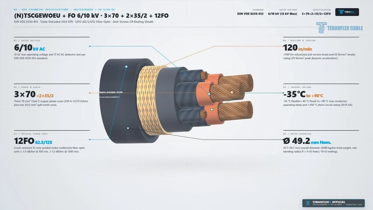
When sizing a crane reel for 120 m/min travel, engineers must check both the nominal tensile rating (20 N/mm²) and the peak acceleration limit (25 N/mm²) in Panel 04 at 0:49 (DIN VDE 0250-813, 2026). For instance, across the three 70 mm² copper phase cores (3 x 70 mm² = 210 mm² total phase copper), 20 N/mm² yields a continuous dynamic pulling force of 4,200 N (~428 kgf). Meanwhile, 25 N/mm² allows 5,250 N (~535 kgf) during crane acceleration and braking peaks. Crucially, the 12FO (62.5/125 µm) optical fiber unit in the third outer interstice must carry zero axial tensile load. Our vulcanized anti-torsion braid (Layer 05) and 210 mm² phase copper absorb the 4,200 to 5,250 N reel tension so optical attenuation stays within max 3.5 dB/km at 850 nm and max 1.2 dB/km at 1300 nm.
Spec Panel (0:49)
01 / RATED VOLTAGE.
- Rated Value on Screen: 6/10 kV AC (
12 kVmax,17 kVtest). - Engineering & Design Significance: Rated for
6/10 kVcrane grids and verified by a 17 kV AC routine dielectric test.
02 / POWER & EARTH.
- Rated Value on Screen: 3x70 + 2x35/2 (
250 A,0.272 Ω/km). - Engineering & Design Significance: Three
70 mm²Class 5 phase cores (210 mm²total) plus two17.5 mm²split earth cores.
03 / OPTICAL FIBER UNIT.
- Rated Value on Screen: 12FO 62.5/125 (
OM1multimode). - Engineering & Design Significance: Crush-resistant 12-core graded-index fiber unit (
max 3.5 dB/km @ 850 nm,max 1.2 dB/km @ 1300 nm).
04 / REELING & TORSION.
- Rated Value on Screen: 120 m/min, ±100 °/m, 20-25 N/mm².
- Engineering & Design Significance: Supports 4,200 N nominal (5,250 N peak) pull and
±100 °/manti-torsion stability.
05 / THERMAL RATING.
- Rated Value on Screen: -35 to +90 °C (
+250 °CSC,10.01 kA). - Engineering & Design Significance: Runs at
-35 °Cflexible (-40 °Cfixed) to +90 °C core temp and 10.01 kA 1s SC.
06 / OUTER DIAMETER.
- Rated Value on Screen: 49.2 mm Nom. (
47.7-50.7 mmOD). - Engineering & Design Significance: Weighs 4,480 kg/km (
4.48 kg/m); min bend radius6 x D(295 mm) fixed /10 x D(492 mm) reeling.
What Do the Real 4K 60fps Video & 4000x3000 Macro Photos Verify at 0:54 to 1:02?
In Section 06 (0:54 to 1:02), our quality team inspected an actual production sample of 6/10 kV (N)TSCGEWOEU+FO 3x70+2x35/2+12FO (62.5/125) (TEBAOFLEX Sample Log, 2026). We used 4K 60fps video, 4000x3000 macro photos, and factory line inspection.
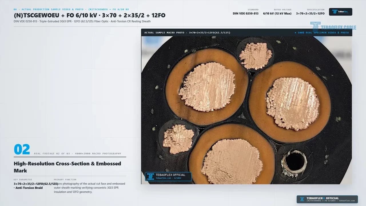
The three real clips cover the end-face video (0:54 to 0:57), macro photos (0:57 to 0:59), and factory line video (0:59 to 1:02). Together, they verify four physical build details.
- Compact 3 x 70 mm² Copper & 3GI3 EPR (
0:55 to 0:58). First, in the4000x3000macro cut above, the three70 mm²copper cores sit inside amber3GI3EPR rings. Thin black inner and outer semi-con screens bound each ring. - Balanced 2 x 35/2 mm² Split Earth & Crush-Resistant 12FO Tube (
0:58). Second, the two35/2 mm²(17.5 mm²) bare copper split earth cores occupy the upper-left and right outer valleys. Meanwhile, the thick-walled12FO (62.5/125 µm)optical buffer tube sits protected in the lower-right valley. - Full-Valley Elastomeric Bedding & Embedded Anti-Torsion Braid (
0:58). Third, the black pressure-extrudedEPR / GM1binner bedding fills every gap around the six elements. Green-tinted anti-torsion braid cords are visibly vulcanized into the sheath wall. - Embossed 2026 Outer Sheath Legend & Factory Line Verification (
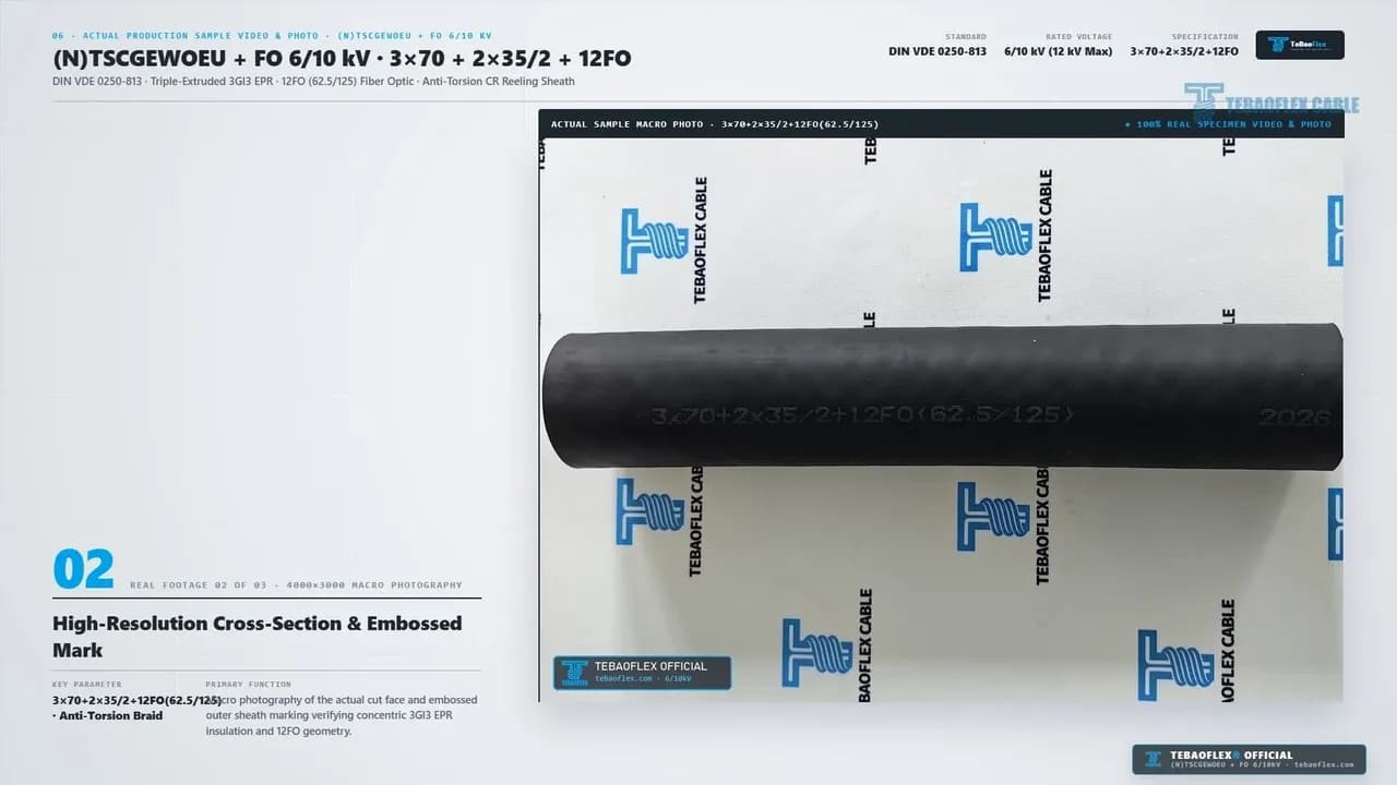
0:59 to 1:02). Fourth, the4000x3000macro photo below (0:59) verifies the permanent embossed sheath mark3x70+2x35/2+12FO(62.5/125) ... 2026. At1:00 to 1:02, real factory clips show the49.2 mmblackCRjacket in the cooling trough and haul-off wheel.
How Do You Size 3x70+2x35/2+12FO Crane Reeling Cables (DIN VDE 0298-4)?
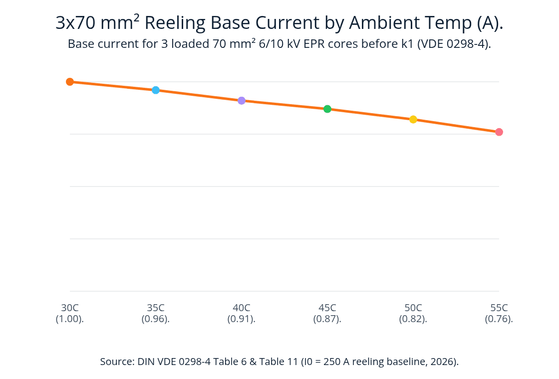
As shown at 0:16, 0:37, 0:46, and 0:49, each 70 mm² (6/10 kV) core has a base current (I₀) of 250 A at 30 °C under DIN VDE 0298-4 (2026).
Crane reel ampacity derating is the thermal sizing calculation under DIN VDE 0298-4 that multiplies the 30 °C baseline current (I₀ = 250 A) by a reel winding factor (k₁) and an ambient temperature factor (k₂).
Iᶻ = I₀ × k₁ × k₂.
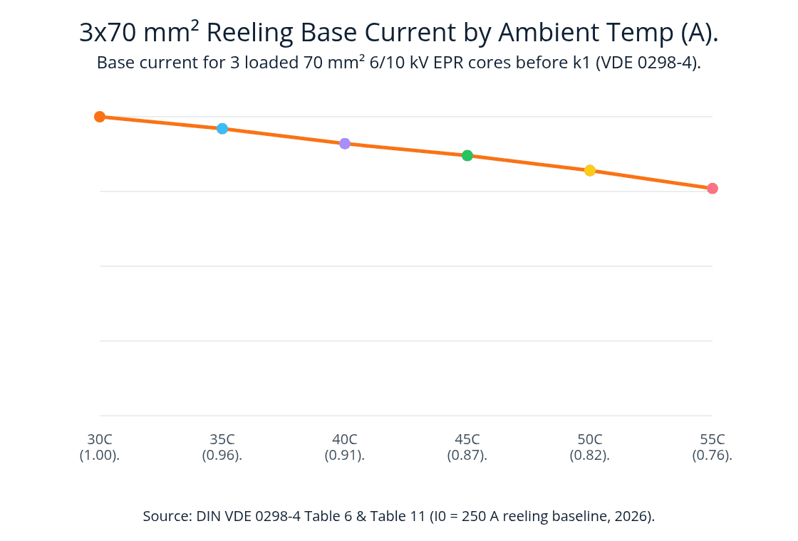
3x70 mm² Reeling Base Current by Ambient Temp (A). line data: 30C (1.00) 250; 35C (0.96) 240; 40C (0.91) 227.5; 45C (0.87) 217.5; 50C (0.82) 205; 55C (0.76) 190. Source: DIN VDE 0298-4 Table 6 and Table 11 (I0 = 250 A reeling baseline, 2026).
Source: DIN VDE 0298-4 Table 6 & Table 11 MV Reeling Ampacity, 2026.
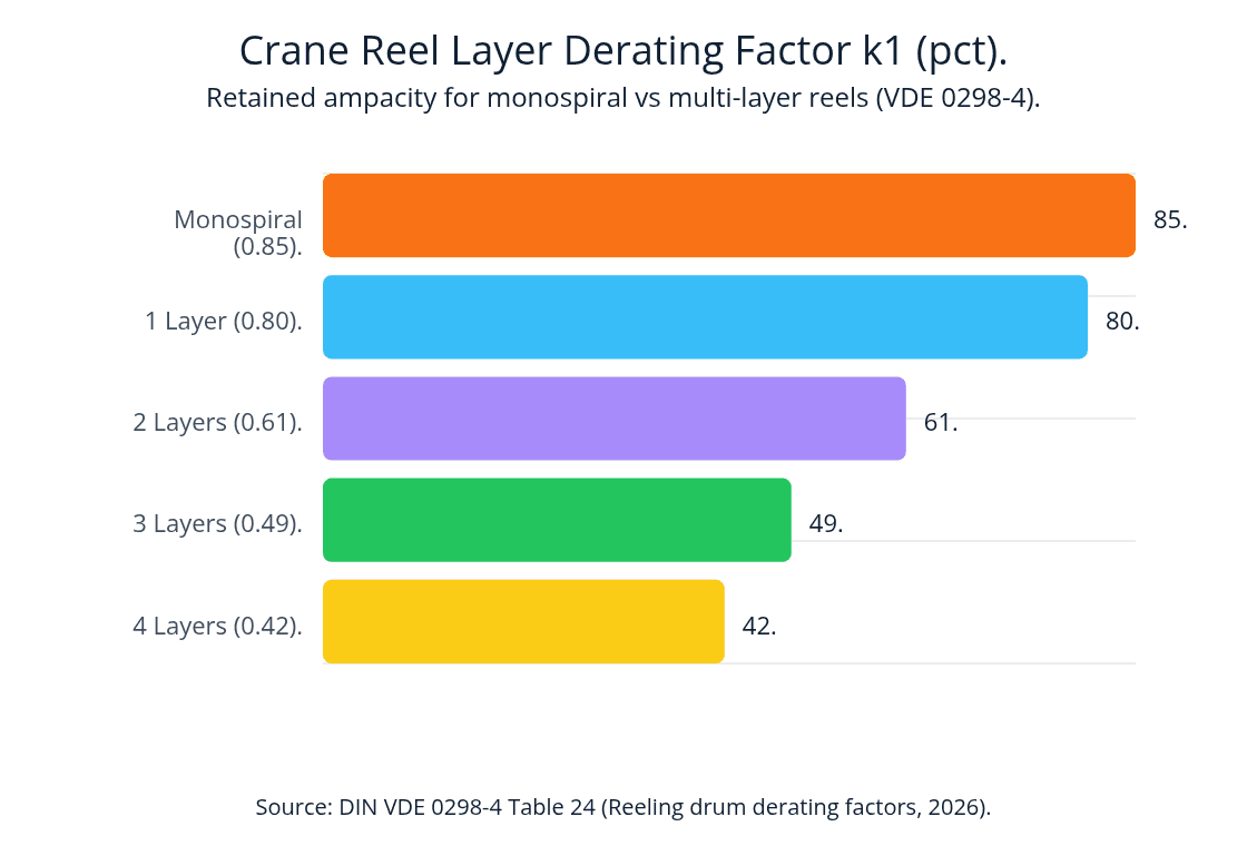
On a ventilated giant monospiral reel (0:08 to 0:21), air circulates between the open spokes, giving a typical winding factor k₁ of 85% (DIN VDE 0298-4, 2026). On a cylindrical multi-layer drum, k₁ equals 80% for 1 layer, 61% for 2 layers, 49% for 3 layers, and 42% for 4 layers (DIN VDE 0298-4, 2026).
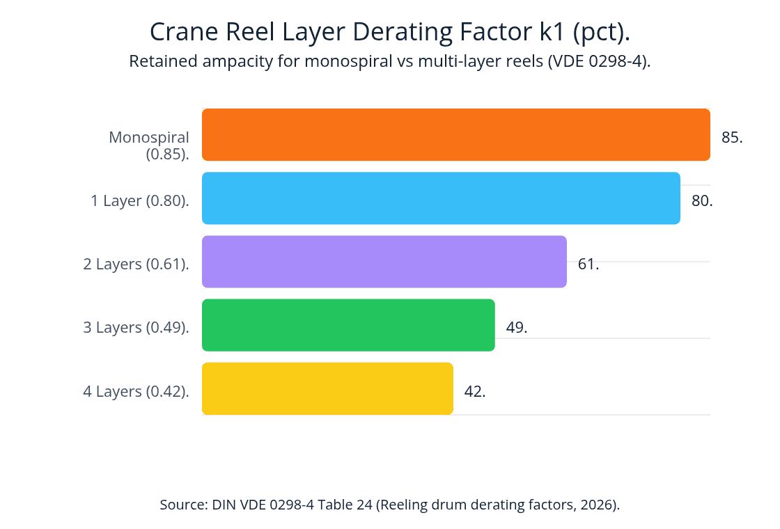
Crane Reel Layer Derating Factor k1 (pct). horizontal bar data: Monospiral (0.85) 85; 1 Layer (0.80) 80; 2 Layers (0.61) 61; 3 Layers (0.49) 49; 4 Layers (0.42) 42. Source: DIN VDE 0298-4 Table 24 (Reeling drum derating factors, 2026).
Source: DIN VDE 0298-4 Table 24 Reeling Drum Derating, 2026.
Reference Ampacity Table for 3x70+2x35/2+12FO Crane Reeling Cables
Consider a 6 kV or 10 kV STS crane or stacker-reclaimer fed through a motorized reel. The table below lists continuous current limits per 70 mm² phase core under DIN VDE 0298-4 (2026).
Reeling Mode (I₀ = 250 A)
Unwound Trench / Base (I₀ = 250 A).
- Reel Factor (k₁):
1.00 - 30 °C (k₂ = 1.00): 250.0 A (
~2.16 MWat6 kV). - 40 °C (k₂ = 0.91): 227.5 A.
- 50 °C (k₂ = 0.82): 205.0 A.
Ventilated Monospiral Reel.
- Reel Factor (k₁):
0.85 - 30 °C (k₂ = 1.00): 212.5 A (
~1.84 MWat6 kV). - 40 °C (k₂ = 0.91): 193.4 A.
- 50 °C (k₂ = 0.82): 174.3 A.
Cylindrical Drum: 1 Layer.
- Reel Factor (k₁):
0.80 - 30 °C (k₂ = 1.00): 200.0 A (
~1.73 MWat6 kV). - 40 °C (k₂ = 0.91): 182.0 A.
- 50 °C (k₂ = 0.82): 164.0 A.
Cylindrical Drum: 2 Layers.
- Reel Factor (k₁):
0.61 - 30 °C (k₂ = 1.00): 152.5 A (
~1.32 MWat6 kV). - 40 °C (k₂ = 0.91): 138.8 A.
- 50 °C (k₂ = 0.82): 125.1 A.
Cylindrical Drum: 3 Layers.
- Reel Factor (k₁):
0.49 - 30 °C (k₂ = 1.00): 122.5 A (
~1.06 MWat6 kV). - 40 °C (k₂ = 0.91): 111.5 A.
- 50 °C (k₂ = 0.82): 100.5 A.
Cylindrical Drum: 4 Layers.
- Reel Factor (k₁):
0.42 - 30 °C (k₂ = 1.00): 105.0 A (
~0.91 MWat6 kV). - 40 °C (k₂ = 0.91): 95.6 A.
- 50 °C (k₂ = 0.82): 86.1 A.
What Should You Send Us for Hybrid Fiber-Optic Reeling Cable Selection?
To help our team confirm the right (N)TSCGEWOEU+FO build for your STS crane, RMG crane, or stacker-reclaimer, send us these 6 details.
- System Voltage & Crane Power Load. State the nominal voltage (
3.6/6 kV,6/10 kV,8.7/15 kV, or12/20 kV), total transformer kVA/MVA, full-load current (A), and trench length (m). - Optical Fiber Type & Channel Count. Confirm whether your crane PLC and optical rotary joint require 12FO (62.5/125 µm OM1),
50/125 µm (OM2/OM3), or9/125 µm (OS2)single-mode fibers (6FO,12FO,18FO, or24FO). - Reel Type & Winding Layers. Specify whether the crane uses a ventilated monospiral reel (
single radial spiral) or a multi-layer cylindrical level-wind drum (number of layers). - Travel Speed, Acceleration & Fairlead Rollers. Share your maximum gantry travel speed (
up to 120 m/minor higher), peak acceleration (m/s²), and minimum fairlead sheave diameter (min bend R = 10 x D = 492 mm). - Trench Entry & Reel Slip-Ring Bore. Provide your cable gland and Kellems grip sizes so we can verify fitment against the 47.7 to 50.7 mm outer diameter window (
49.2 mmnominal OD). - Pre-Shipment FAT & OTDR Test Requirements. Let us know if you need batch test certificates (17 kV AC 5-min test,
20 °CDC resistance, and850 / 1300 nmOTDR optical attenuation traces) before dispatch.
Frequently Asked Questions (FAQ)
What does the designation (N)TSCGEWOEU+FO 6/10 kV 3x70+2x35/2+12FO mean under DIN VDE 0250-813?
In German VDE codes, (N) indicates national standard adaptation (DIN VDE 0250-813), TSC denotes a heavy-duty medium-voltage reeling cable, and GE specifies triple-extruded 3GI3 EPR insulation with semi-con layers. W indicates weather and water resistance, O denotes an anti-torsion braid, EU specifies a flame-retardant, oil-resistant polychloroprene (CR / 5GM5) double sheath, and +FO denotes the integrated 12-core (62.5/125 µm) optical fiber unit.
Why are there two 35/2 mm² split earth cores instead of three in this hybrid +FO cable?
In a standard non-fiber cable, three split earth cores fill the three outer valleys. In this 3x70+2x35/2+12FO hybrid cable, two 35/2 mm² (2 x 17.5 mm² = 35 mm² total) split earth cores occupy two outer valleys while the 12FO (62.5/125 µm) optical fiber unit occupies the third valley (0:31 and 0:58). This keeps the cable perfectly circular (49.2 mm nominal OD) without adding a second layer of cores.
How is the 12FO (62.5/125 µm) fiber-optic unit protected during 120 m/min high-tension reeling?
First, the 12 graded-index multimode fibers sit inside a crush-resistant buffer tube nested in the third outer interstice between two 70 mm² phase cores (0:31 and 0:58). Second, the pressure-extruded EPR / GM1b inner bedding (Layer 04) and vulcanized anti-torsion braid (Layer 05, ±100 °/m) lock the core geometry so the three 70 mm² copper cores absorb the 4,200 N (5,250 N peak) pull. This keeps optical attenuation at or below 3.5 dB/km at 850 nm and 1.2 dB/km at 1300 nm.
What is the maximum pulling force and minimum bending radius for the 49.2 mm OD cable?
Under DIN VDE 0250-813, the three 70 mm² copper phase cores (210 mm² total) support 20 N/mm² continuous dynamic pull (4,200 N) and 25 N/mm² peak acceleration pull (5,250 N). The minimum bending radius is 6 x D (295 mm) for fixed routing and 10 x D (492 mm) for dynamic reeling.
Does the 68-second video show real production sample footage or only 3D animations?
The 68-second video combines 100% real 4K 60fps sample video, 4000x3000 macro photos, and factory extrusion clips (0:00 to 0:03 and 0:54 to 1:02 per TEBAOFLEX Video Log, 2026) with schematic 3D animations (0:03 to 0:54). The real footage verifies the razor-cut 3x70+2x35/2+12FO cross-section (0:55 to 0:58), the embossed sheath mark 3x70+2x35/2+12FO(62.5/125) ... 2026 (0:59), and the 49.2 mm black CR jacket on the factory line (1:00 to 1:02).
Request a Specification Check or Custom Fiber-Optic Crane Reel Quote
Planning a port STS/RMG crane upgrade, stacker-reclaimer reel replacement, or automated mining project with 6/10 kV TEBAOFLEX (N)TSCGEWOEU+FO 3x70+2x35/2+12FO (62.5/125)? Please contact our engineering team or browse our Reeling Cable Catalog and Port & Material Handling Crane Solutions to get a datasheet and quote.
Contact TEBAOFLEX on WhatsApp: +86 185 9591 3361