Case study
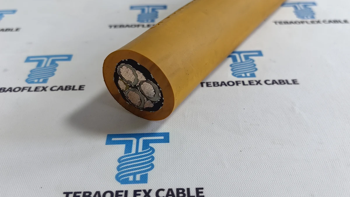
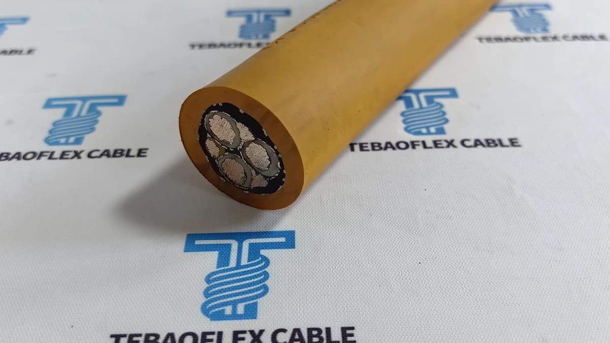
TEBAOFLEX supplied an orange 2000V Type SHD-GC 3x6 AWG + 2x10 AWG + 1x10 AWG cable for a mining electrical distributor in Peru under order reference TBLT2612. This case follows the selection discussion, conductor and shield construction, workshop photographs, dimensional inspection and export packaging described in the project material.
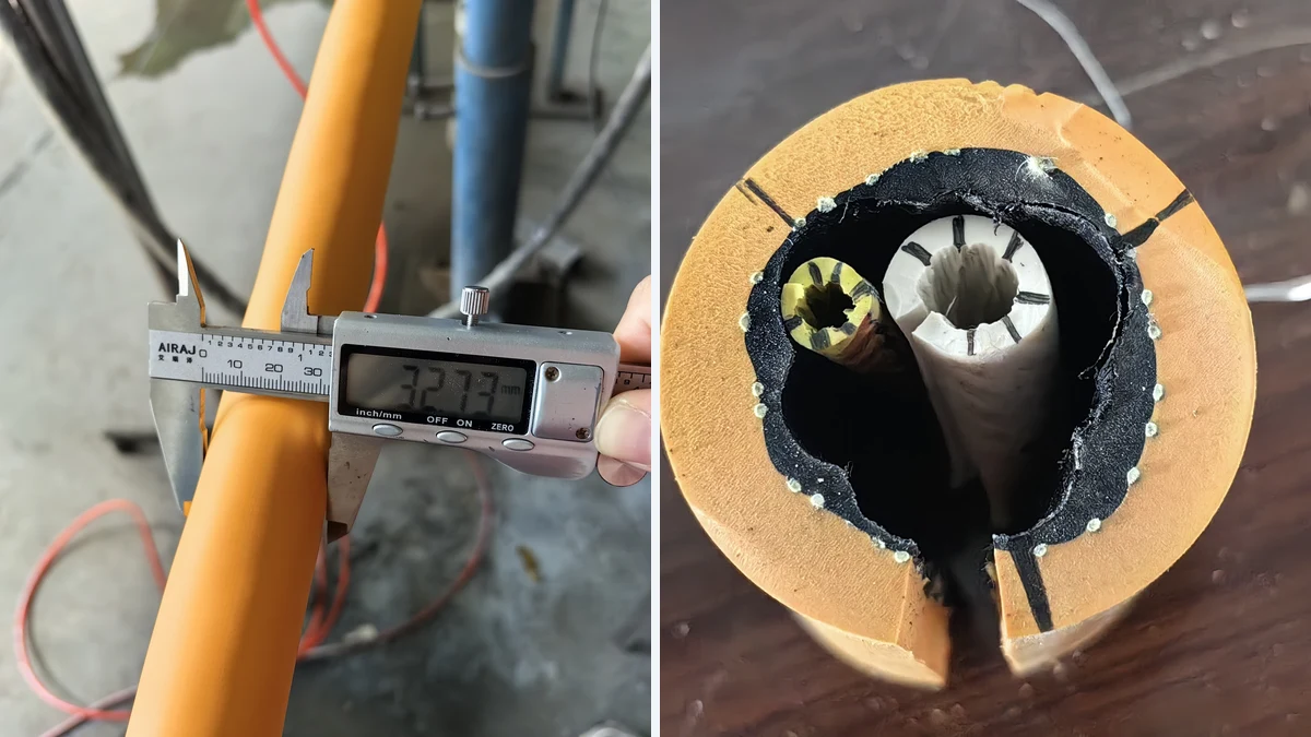
The photographs include a digital caliper reading of 32.73 mm on a cable sample. This is a photographed measurement, not a universal diameter or acceptance limit for all SHD-GC cables. The page does not replace the approved order drawing, drum-specific factory test report or any required certification.
Case at a Glance
- Customer and destination: Mining electrical distributor in Peru; Callao is the destination reported in the case file.
- Order reference: TBLT2612
- Cable designation: Type SHD-GC 2000V, 3x6 AWG + 2x10 AWG + 1x10 AWG
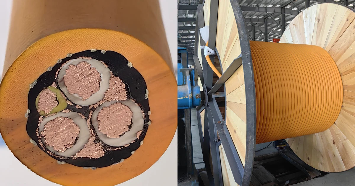
- Phase conductors: Three 6 AWG tinned copper conductors, approximately 13.3 mm² each, with EPR insulation.
- Ground and ground-check conductors: Two bare 10 AWG grounding conductors and one yellow-insulated 10 AWG ground-check conductor; approximately 5.26 mm² each.
- Shielding and reinforcement: Individual copper/textile phase braids and an aramid reinforcing mesh over the inner bedding, as described in the supplied construction narrative.
- Outer jacket: Orange heavy-duty jacket. Confirm the delivered compound from the approved order specification; the colour does not identify TPU or CPE.
- Inspection photograph: 32.73 mm outer-diameter reading on the photographed sample.
- Quantity scope: Initial enquiry: 2,000 m. The delivery described in the case file: one 1,000 m drum. These are different stages of the enquiry and supply, not interchangeable quantities.
The Application: Reviewing a Mining Distributor's Requirements
The initial enquiry considered two 2 kV cable configurations: SHD-GC (EPR-TPU) 3x8+2x10+1x12 AWG and G-GC (EPR-TPU) 3x8+2x10+1x10 AWG. These are recorded enquiry options, not validated product specifications. The final configuration described for this delivery was SHD-GC 3x6+2x10+1x10 AWG, 2000V.
The buyer's application discussion covered continuous miners, longwall equipment, shuttle cars, roof bolters, blast-hole drills and mine pumps. These are potential application categories, not evidence that the delivered cable has been installed or field-qualified on all six types of equipment.
The engineering review needed to consider phase conductor size, the ground-check circuit, machine current, cable handling and jacket exposure together. A larger phase conductor does not by itself establish suitability for a specific reel, mine or protection system. Confirm bending radius, allowable pull, torsion, travel speed, duty cycle and electrical protection against the approved cable and machine specifications.
For related application information, see Mining & Tunnelling Cable Solutions and the Trailing Cable range.
Construction: Phase Shields, Ground Check and Reinforcement
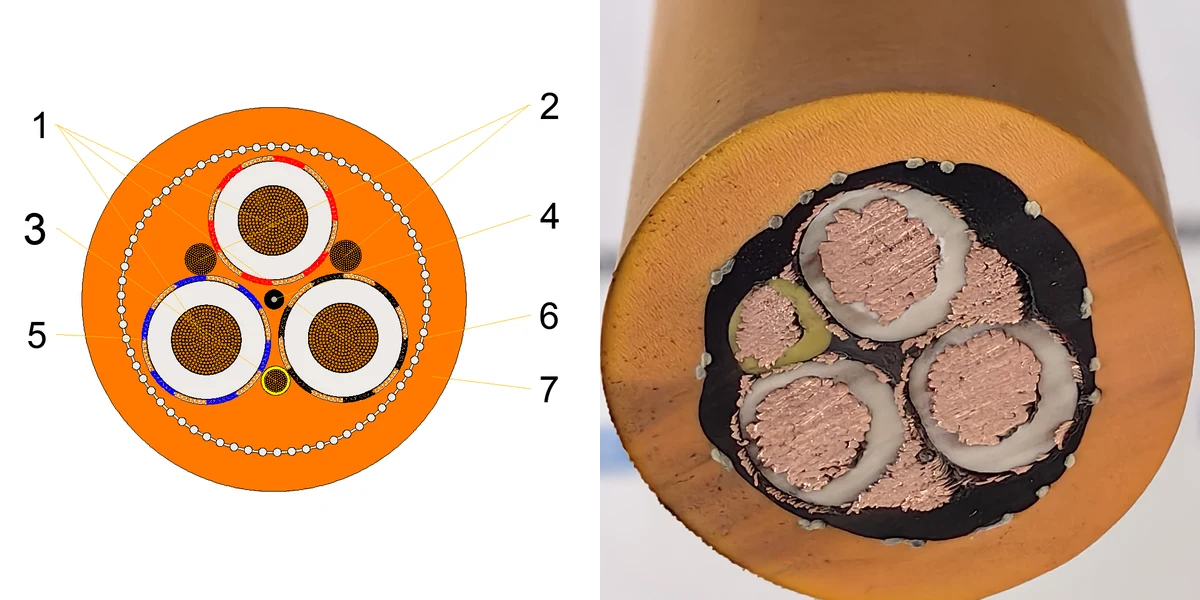
The distinguishing feature discussed here is the individual metallic braid around each insulated phase, together with grounding conductors and a separate ground-check conductor. The ground-check core belongs to the monitoring circuit; it is not a substitute for a protective grounding conductor.
Grounded phase shields can provide a fault-current path, but clearing a fault depends on continuity, bonding, the protection system and its settings. A shield cannot guarantee that a crushed cable will trip before an arc occurs. Installation and protection coordination require a qualified engineer's review.

The illustration is explanatory rather than a dimensioned manufacturing drawing. The component groups below describe the supplied case construction; they are not seven concentric layers or a universal SHD-GC specification.
- Phase conductors: Three flexible 6 AWG tinned copper conductors. Material identity and stranding should be traceable to the approved manufacturing specification.
- Grounding conductors: Two bare 10 AWG tinned copper conductors in the spaces between the phase cores, arranged to contact the metallic shields.
- Ground-check conductor: One yellow-insulated 10 AWG conductor. The case material names alternative insulation compounds, so the delivered compound must be confirmed from the order drawing.
- Fillers and bedding: Black elastomeric fillers and inner bedding support the assembled cores and the reinforcing mesh.
- Phase insulation and shields: EPR insulation with individual copper/textile braid shields. The case narrative gives 1.78 mm (70 mils) nominal insulation and a minimum 60% braid-coverage design target; these are not independently verified measurements on this page.
- Reinforcement: Aramid mesh over the inner bedding. Its function is mechanical reinforcement; no tensile limit, torsional qualification or cycle-life result is established by the photographs.
- Outer jacket: Orange jacket, with 3.94 mm (155 mils) nominal wall stated in the case narrative. The photographed OD is 32.73 mm; use the approved dimensional limits for acceptance and accessory sizing.
Workshop Sequence Shown in the Case Material
1. Conductor and Insulated-Core Preparation
The manufacturing narrative describes flexible tinned copper stranding, EPR insulation on the phase conductors and yellow insulation on the ground-check core. The three phase cores and the ground-check core have different electrical functions and must remain identifiable during assembly and termination.
2. Phase Braiding, Cabling and Reinforcement
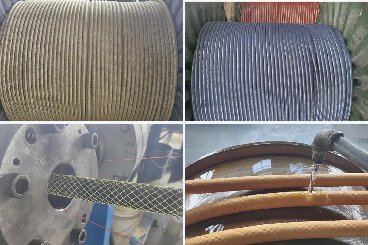
The production photographs show braided phase cores, coloured textile identification and an open reinforcing mesh being applied over the inner bedding. The described assembly brings together three shielded phase cores, two grounding conductors and one insulated pilot core with fillers. Braid coverage and material identity need manufacturing inspection records; an image alone cannot establish either a numerical coverage value or service life.
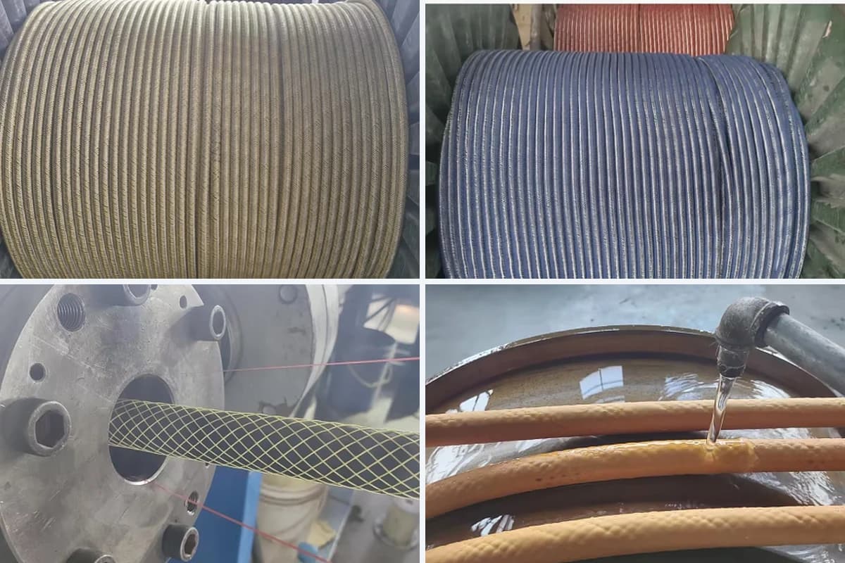
3. Jacket Application and Identification
The final jacket process depends on the selected compound: a thermoset construction requires its specified curing process, while a thermoplastic construction is cooled after extrusion. The cooling photograph does not establish the polymer grade. Jacket markings should match the delivered voltage, conductor configuration, compound designation and the standards or approvals actually applicable to that order.
TPU and CPE: Confirm the Actual Compound Before Reordering
The enquiry discussed TPU, while the source narrative also included a CPE marking example. That example is not sufficient to identify the delivered jacket. For a repeat order, confirm the compound, grade and jacket marking against the approved specification rather than inferring the material from its orange colour.
TPU and CPE should be compared using grade-specific data and the actual operating environment. Neither material name alone establishes abrasion life, minimum operating temperature, chemical compatibility or flame-test performance.
- Abrasion, cuts and dragging: The stated test method, compound grade and comparable results. Laboratory abrasion loss is not a direct prediction of service life on sharp rock.
- Cold bending and repeated movement: Minimum temperature for the intended duty, bending radius and relevant flexing or reeling test conditions.
- Oil, water and chemical contact: Compatibility with the actual fluid, concentration, temperature and exposure duration; do not assume resistance to every acid or solvent.
- Heat and flame requirements: The cable's declared temperature rating and the report or approval for the applicable flame test. These are not interchangeable qualifications.
When comparing abrasion reports, specify the method and edition. DIN lists DIN 53516 as withdrawn and replaced by DIN ISO 4649:2006-11. Do not rename a laboratory abrasion test as a rock-drag field trial or convert an abrasion ratio into a guaranteed life multiplier.
Ampacity: A Calculation Example, Not a Reel Rating
The original comparison used 93 A for 6 AWG and 72 A for 8 AWG at a stated 90°C conductor temperature and 40°C ambient air. For context, Prysmian's published 2 kV SHD-GC data list 93 A for its 6 AWG construction under those temperature assumptions. A different manufacturer's rating is a comparison reference, not certification of this TEBAOFLEX cable.
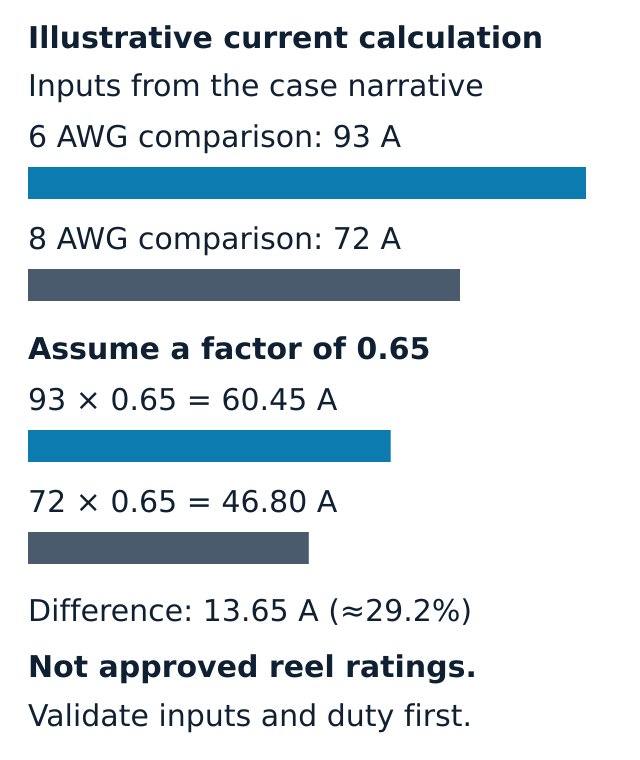
The illustration below retains the case narrative's 93 A and 72 A inputs only to explain the arithmetic. If an application-specific assessment justified a factor of 0.65, the calculated currents would be 60.45 A and 46.80 A. The resulting difference is 13.65 A, approximately 29.2%. The 72 A input and the 0.65 factor are not validated ratings for the proposed 8 AWG construction or this reel.

- Base inputs from the case narrative: 6 AWG comparison input 93 A; 8 AWG comparison input 72 A.
- Conditional calculation: 93 × 0.65 = 60.45 A; 72 × 0.65 = 46.80 A.
- Difference: 13.65 A; (93 ÷ 72 − 1) × 100 ≈ 29.2%.
Do not use these values to set protection or select a reel without validating the cable construction, ambient conditions, number of wound layers, reel geometry, ventilation, duty cycle and manufacturer's installation guidance. This page does not claim that 0.65 is a universal two-layer factor prescribed by ICEA.
Factory Inspection: What the Photographs Establish

The left photograph shows a 32.73 mm caliper reading. The right photograph shows a stripped section with radial inspection marks. These images illustrate a sample measurement and the preparation of a wall-inspection sample; they do not establish dimensional compliance along the entire drum.
The supplied narrative describes factory testing, but the signed drum-specific FAT report and individual test records are not included in the published evidence. Accordingly, this page does not reproduce the uncorroborated electrical, wall-thickness, braid-coverage or combustion values as verified results, and does not present a blanket PASS table.
For acceptance or a repeat order, request a traceable report covering:
- Drum and batch identity, actual tested length and the approved specification revision.
- Dimensions, sampling locations, applicable minimum and maximum limits, and calibrated equipment.
- Conductor resistance with test temperature and length correction.
- Insulation resistance with voltage, duration, temperature and length normalization.
- Withstand voltage, duration, connection arrangement and recorded outcome.
- Any required flame-test report and approval identification, with the applicable construction and scope.
30 CFR § 7.407 specifies testing three specimens. Its 204.4°C value concerns conductor preheating, not burner temperature; each specimen must satisfy the specified afterburn and char-length limits. A single summary reading is not enough to verify that procedure. This case page makes no claim that the supplied cable holds MSHA approval.
Export Drum Packaging and Shipment to Peru
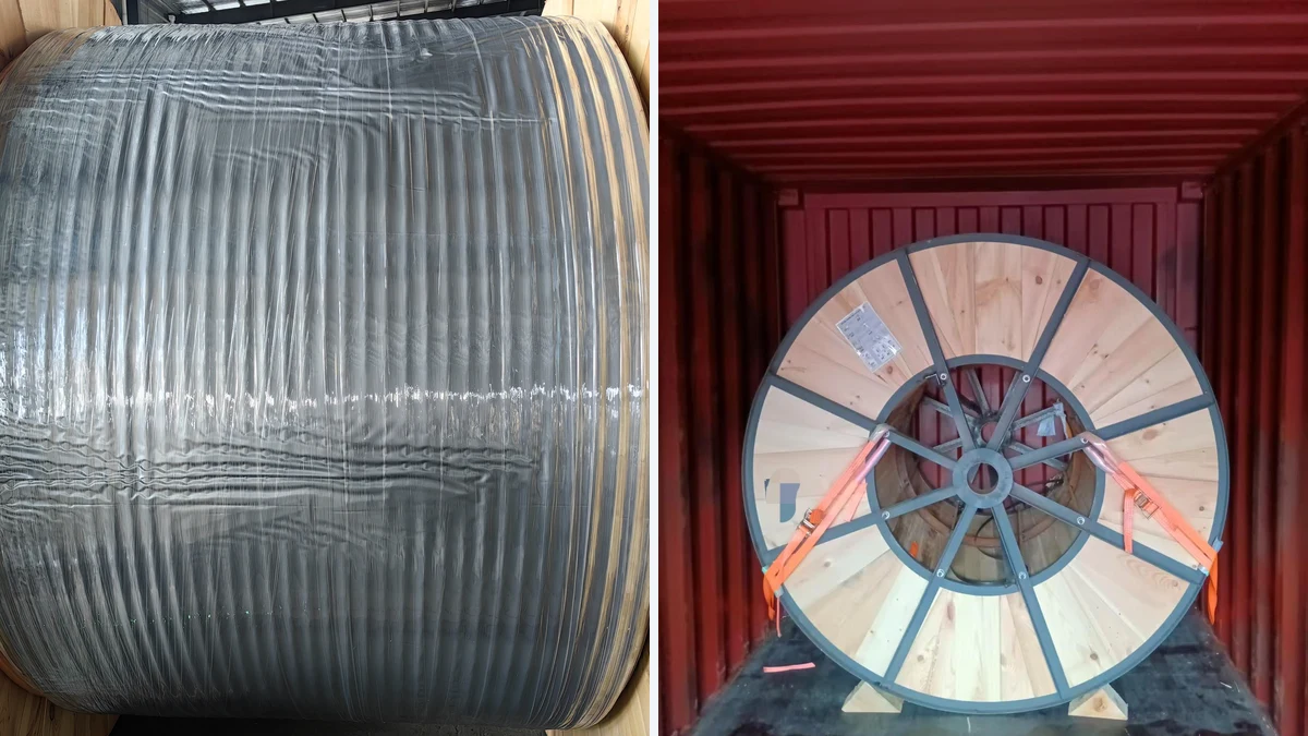
The case file describes one 1,000 m length wound onto a steel-framed wooden export drum for shipment to Callao, Peru, and identifies container MSMU1463135. The initial 2,000 m enquiry is a separate quantity; the supplied material does not explain the commercial change or establish delivery of the remaining quantity.

The photographs show protective wrapping and an export drum positioned inside a container with restraint straps. They illustrate packaging and loading, not proof of final receipt or operational performance at a mine. Use the packing list and transport documents to reconcile the shipped length, drum identity and container reference.
OEM marking and confidentiality requirements should be agreed before production. The case narrative gives a typical manufacturing lead time of 25–45 days; a current quotation must confirm the actual schedule, specification and marking requirements.
Frequently Asked Questions
Why consider SHD-GC rather than G-GC?
This case uses individual phase shields and a separate ground-check conductor. Whether that arrangement is required or suitable depends on the machine, power system, applicable specification and protection design. It does not guarantee safe operation after mechanical damage.
Was this delivery TPU or CPE?
The supplied material discusses both and does not consistently identify the final jacket. Confirm the delivered compound from the approved order specification before placing a matching order; the orange jacket and a generic marking example are not sufficient evidence.
Is 32.73 mm the standard diameter for 6 AWG SHD-GC?
No. It is the reading visible in this case's caliper photograph. Diameter varies with construction; gland selection, bending clearances and acceptance must use the approved cable drawing and its tolerances.
Can the current calculation be used as a reel setting?
No. It is an illustrative calculation using stated inputs and an assumed correction factor. Obtain the applicable current rating and reel-duty assessment before setting protection or selecting the cable.
Discuss a Mining Cable Specification or Request the Order Documents
Send the equipment type, operating voltage, load profile, required length, cable-handling arrangement and site conditions to the TEBAOFLEX engineering team. For a matching supply, quote TBLT2612 and request the approved construction, jacket compound, drum-specific FAT documentation and relevant approval evidence.