

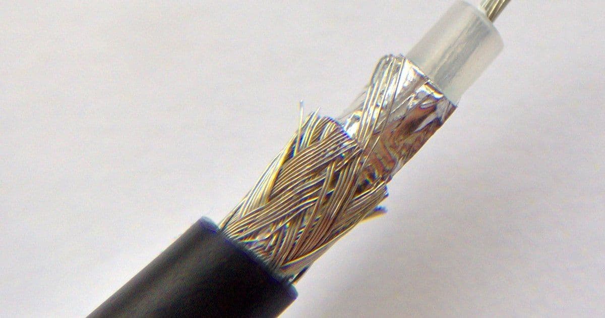
A shielded cable carries at least one screen, or shield: a conductive or semiconductive layer whose job changes from one cable type to another. A technical specification from the International Electrotechnical Commission (IEC) names the best-known job: "Screening (or shielding) is one basic way of achieving electromagnetic compatibility (EMC)." The two words name the same kind of layer. IEC documents mostly say "screen", while Institute of Electrical and Electronics Engineers (IEEE) guides and US regulations say "shield".
This guide compares three screening applications: EMC screens on drive, control and data cables; medium voltage (MV) screens; and earth screens with ground check on mining cables. Mechanical armour is included as a separate comparison, not as an automatic fourth type of screen. Each job has its own standards, test methods and regulations. A datasheet line such as "braid screen" means little until the job is known.
Key Takeaways
- Braid coverage is a construction value, while IEC 62153-4-3 measures a screen's surface transfer impedance, using a triaxial method that captures only the magnetic component.
- Earthing practice depends on the sector: Federal Aviation Administration (FAA) guidance says screened aircraft wiring is "typically connected to the aircraft's ground at both ends".
- MV screens sit in power-cable standards: IEC 60502-2 covers extruded-insulation cables from 6 kV to 30 kV for fixed installations, excluding mining-industry cables.
- US mine rules in the Code of Federal Regulations (CFR) at 30 CFR 75.804 call for "metallic shields around each power conductor" of underground high-voltage cables in "resistance grounded systems".
- Armour has its own clause: the 2014 text of IEC 60502-2 lists "13 Metal armour" separately from its conductor screen, insulation screen and metal screen clauses.
Shielded Cable Types at a Glance
The table compares three screening applications and, separately, mechanical armour. Each has its own construction and specification points. A layer called a screen on one datasheet may do none of the jobs of a screen on another.
- Layer or application: EMC screen — Typical construction: Tinned copper wire braid, foil tape, or braid plus foil, overall or around each core — What it does: Acts as an outer conductor that helps limit electromagnetic interference (EMI) — What to specify: Construction, transfer impedance (Zt) or screening attenuation data, termination hardware
- Layer or application: MV screen — Typical construction: Semiconductive conductor and insulation screens, plus a metallic screen such as concentric copper wires — What it does: Our pages call the semiconductive layers stress-control layers and the wire layer a protective screen — What to specify: Screen type and cross-section, bonding method
- Layer or application: Mining earth screen — Typical construction: Metallic screen or braid on each power core, ground conductors and a ground-check conductor — What it does: Serves as a protective-earth screen; a ground-check circuit opens the breaker if the ground or ground-check wire breaks — What to specify: Per-core screens, ground conductors, ground check, monitoring, jurisdiction
- Layer or application: Armour braid (mechanical protection; not automatically an EMC screen) — Typical construction: Galvanised steel-wire braid, for example — What it does: Protects the cable mechanically — What to specify: Armour type and a separate protective conductor
Ask which job a screen does before comparing two datasheets. On our datasheets, a tinned copper braid appears both on EMC festoon cables and, as a protective-earth screen, on each phase of a flexible MV cable.
EMC Screens: Braid, Foil or Both
An EMC screen is a metallic covering, made as a braid, a foil or both, that limits interference from stray electromagnetic energy. FAA Advisory Circular 43.13-1B defines shielding, in paragraph 11-89, as "the process of applying a metallic covering to wiring and equipment to eliminate interference caused by stray electromagnetic energy." The same paragraph says EMI occurs when fields "induce high-frequency (HF) voltages in a wire or component". Shielding, it adds, helps by protecting the primary conductor "with an outer conductor."
IEC TS 62153-4-1, published in January 2014, treats screening as a route to EMC. It also warns that "a confusingly large number of methods and concepts" exists for testing the screening quality of cables. That variety is one reason to ask for a named test method rather than a general claim of good screening.
Our datasheets list three braid arrangements. The PUR-C-HF festoon cable, a 0.6/1 kV polyurethane (PUR) design, has a tinned copper wire braid with at least 80 % coverage. The NGFLCGÖU flat festoon cable screens every insulated core separately, each with its own tinned copper wire braid. The TRM-J flexible mining cable, rated 0.69/1.15 kV, lists a concentric braid of 0.30 mm tinned copper wires with at least 90 % coverage.
Foil and braid trade coverage against flexibility. Our shielded-cable page notes that foil gives high coverage but may suit repeated bending less well than a flexible braid. The same page links a braid's wire size, braid angle and coverage to how it flexes and how it behaves electrically.
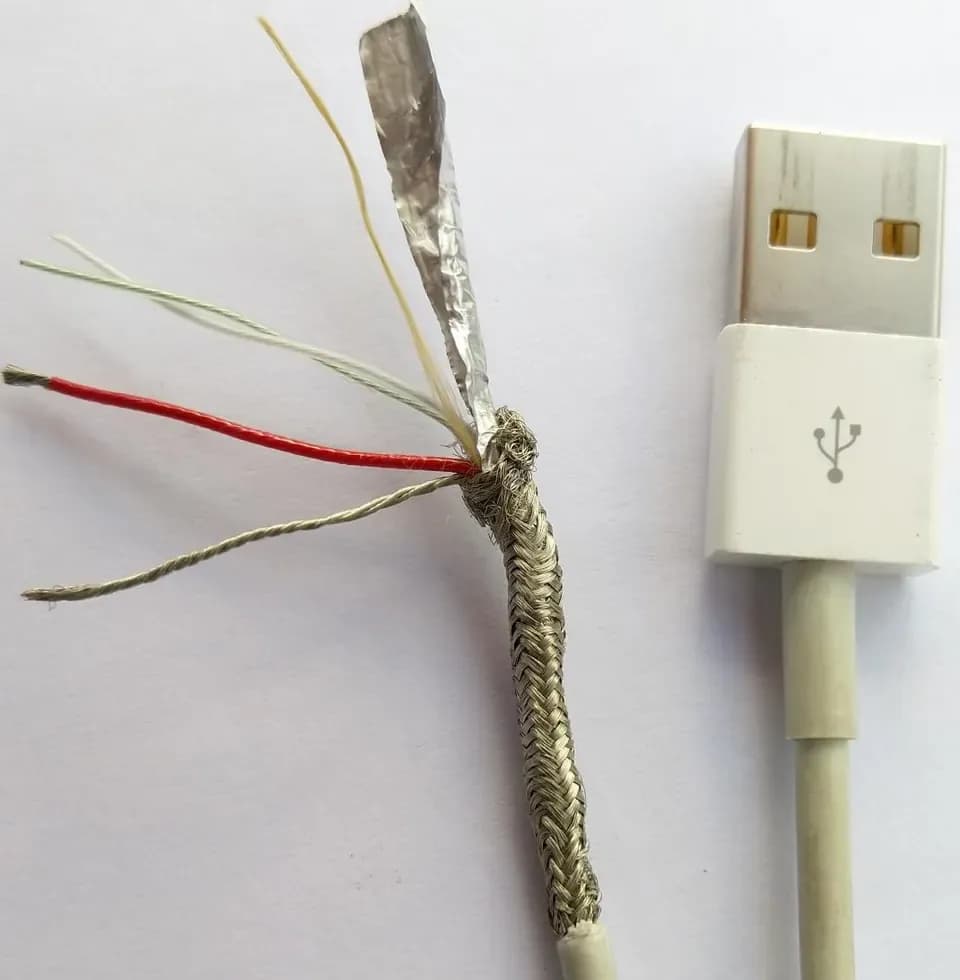
Two ends of the same USB cable, one cut open to show the braid, the foil and a bare ground wire around the insulated conductors. Photo: "Braid and foil shielded usb cable" by Anordal, CC BY-SA 4.0, via Wikimedia Commons, resized.

Transfer Impedance, Not Coverage, Measures a Screen
Screen performance is measured with quantities such as transfer impedance and screening attenuation, while braid coverage is a construction value that describes the braid, not its result. IEC 62153-4-3 sets out a triaxial method. It applies a defined current and voltage to the cable screen and measures the induced voltage to determine the surface transfer impedance. Its abstract adds that the test "measures only the magnetic component of the transfer impedance."
Screening attenuation is another measure. IEC 62153-4-4 describes a method for the screening attenuation of metallic communication cable screens, from low frequencies up to approximately 4 GHz. Thanks to a concentric outer tube, its abstract says, the results are "independent of irregularities on the circumference and outer electromagnetic field."
Braids get their own treatment: the preview contents of IEC TS 62153-4-1 include a clause on the "Transfer impedance of a braided wire outer conductor or screen". For the 0.6/1 kV (N)GRDGCGÖU energy-chain cable used on cranes, our datasheet lists braid coverage above 80 % and a Zt below 100 mΩ/m at 30 MHz. These are design values from our page, not test results.
NASA-HDBK-4001A, approved in July 2025, covers uncrewed spacecraft. For pyrotechnic subsystems, it calls for "cable shielding" that provides at least 40 dB of radio-frequency attenuation from 30 kHz to 40 GHz. The same passage adds a minimum of 85 % optical coverage, with no gaps or discontinuities, including at connector backshell terminations. That figure applies to spacecraft pyrotechnic circuits only, and even there coverage never stands alone.
Terminating and Earthing EMC Screens
How a screen is terminated and earthed depends on the system. The sources describe practice for their own sectors rather than one universal rule. For uncrewed spacecraft, NASA-HDBK-4001A says cable screens "should be terminated at all ends to maximize shielding effectiveness", as part of a near-equipotential design.
The handbook says "360-degree shield terminations provide the lowest impedance". Its pyrotechnic section names a 360° peripheral termination into connector backshells as the preferred method. Pigtail terminations, it warns, "severely degrade cable and harness shielding effectiveness", so their use "is strongly discouraged". The same pyrotechnic section says "Shielding should not be used to carry any intentional currents."
In aircraft, paragraph 11-89 of the FAA circular says "Shielded wire or cable is typically connected to the aircraft's ground at both ends of the wire, or at connectors in the cable." Paragraph 11-232 of the circular asks for "special attention" to "the termination of individual and overall shields" where EMI protection is required. It also lists backshell adapters made for that purpose.
For low-voltage cables, the IEEE 1143-2012 guide gives "Suggestions on terminating and grounding methods", not a fixed rule. IEEE has listed it as "Inactive-Reserved" since 30 March 2023, and a revision project, P1143, was approved on 21 September 2022. At installation level, IEC TR 61000-5-2, a 1997 technical report, gives guidelines for the earthing and cabling of electrical and electronic systems aimed at EMC.
A screen works only as well as its termination. Our PUR-C-HF page treats coverage as one factor, naming routing, gland design, bonding surfaces, 360° termination and braid continuity as influences on the installed result. The same page favours a 360° gland at both ends for the best EMC result, with one-end termination where the system design calls for it.
Screens on VFD Motor Cables
A screen on a variable-frequency drive (VFD) motor cable is one part of the drive system's EMC and earthing design. IEC 61800-3:2022 specifies EMC requirements for adjustable speed power drive systems with input or output voltages up to 35 kV AC RMS. IEC TS 60034-25:2022 covers AC machines on converter supplies, including installation guidance, and its 2022 edition modified clause 8 "to update shaft currents section".
The US Department of Energy (DOE) Motor Systems Tip Sheet #15 advises "minimizing the cable length from the VFD to the motor" on new installations. It warns that VFD voltage overshoots depend on "both cable length and rise time". On bearings, it says "proper cabling and grounding practices may help reduce bearing damage, called fluting", which VFD-induced shaft currents cause.
Our 2 kV VFD mining power cable combines three power conductors, three grounding conductors and a separate ground-check conductor with a braid-and-foil screen. Its datasheet pairs a tinned copper braid with an aluminium/polyester tape for 100 % coverage. For the overall screen, the page points installers to the drive system's EMC and earthing design for termination.
MV Cable Screens: Semiconductive Layers and Metal
MV screens combine semiconductive layers on the conductor and the insulation with a metallic screen, such as concentric copper wires. IEC 60502-2 specifies the construction, dimensions and tests of extruded-insulation power cables from 6 kV up to 30 kV for fixed installations, such as distribution networks. It excludes cables for special conditions, including those for the mining industry and for shipboard use. The consolidated edition 3.1 was published on 30 May 2024, and a corrected version followed in July 2026.
The 2014 text lists separate clauses for the "Conductor screen" (7.2) and the "Insulation screen" (7.3). Others cover "Metal screens not associated with semi-conducting layers" (10.3) and the "Concentric conductor" (11). It also lists "Resistivity of semi-conducting screens" (18.2.10), a normative Annex D on measuring that resistivity, and Table B.1, "Nominal screen cross-sectional areas". Another heading names 3.6/6 kV cables "having unscreened insulation", a reminder that screen construction varies even within one standard.
IEEE 575-2014 is a guide to bonding the screens and sheaths of single-conductor cables rated 5 kV to 500 kV. It describes the most common "shield/sheath-bonding systems" and how to calculate the screen and sheath voltages and currents in three-phase service. IEEE has listed it as "Inactive-Reserved" since 27 March 2025, the day a successor project, P575, was approved. Our shielded-cable page notes that an MV metallic screen may also form part of the fault-current path.
The NTMCGCWÖU single-core cable, based on DIN VDE 0250-813 from 3.6/6 kV to 18/30 kV, has inner and outer semiconducting layers that our page calls stress-control layers. It adds a concentric protective screen of tinned copper wires. Our 6/10 kV (N)TSCGEW11Y shore power cable has semiconductive screens on its main cores, which are insulated with ethylene propylene rubber (EPR). It also has a screened group of eight EPR pilot cores.
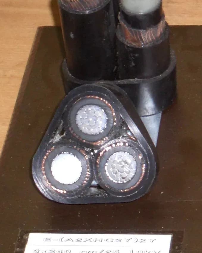
A 10 kV three-core cable sample, with copper wires around each insulated core. Photo: "Mittelspannungskabel 10kV (H-Kabel)" by Wdwd, CC BY-SA 3.0, via Wikimedia Commons, cropped.

Mining Cables: Earth Screens and Ground Check
Under 30 CFR 75.804(a), underground high-voltage cables in "resistance grounded systems" need a metallic screen around each power conductor, plus ground conductors and a ground-check conductor. The ground conductors must total at least half the power conductor's cross-sectional area. Ground-check conductors must be insulated and at least No. 8 American Wire Gauge (AWG) if external, or No. 10 AWG if internal. Paragraph (b) says splices "shall provide continuity of all components".
30 CFR 77.804 applies a similar rule to surface high-voltage trailing cables in "resistance grounded systems". Under 30 CFR 77.803, a fail-safe ground-check circuit must open the circuit breaker if either the ground or the ground-check wire breaks. 30 CFR 75.822 lets high-voltage longwall cables be type SHD with a centre ground-check conductor of at least No. 16 AWG, stranded. 30 U.S.C. 801 places "the primary responsibility" for preventing unsafe conditions on mine operators, "with the assistance of the miners".
WorkSafe WA guidance for Western Australia says trailing and reeling cables must conform to AS/NZS 2802:2000, which excludes underground coal mining. Each needs a pilot core arranged to cut off the supply if the earthing circuit breaks. If the pilot earth continuity circuit is open-circuit or short-circuit, an interlock "must immediately initiate automatic de-energisation of the mobile apparatus."
On our (N)TSCGECEWÖU flexible MV cable, each EPR-insulated phase has its own braided protective-earth screen of tinned copper wires. Our Type SHD-GC portable mining cable, rated 2 kV to 25 kV, screens each EPR power core. It typically adds two grounding conductors and an insulated ground-check conductor. Screened South African cable types appear in our SANS 1520 guide.
On high-voltage longwalls, 30 CFR 75.814(e) requires ground-wire monitoring on each cable where two or more high-voltage cables supply a common bus in a high-voltage enclosure. The chart below plots the ground-fault limits in 75.814(a), which likewise apply only to high-voltage longwalls.
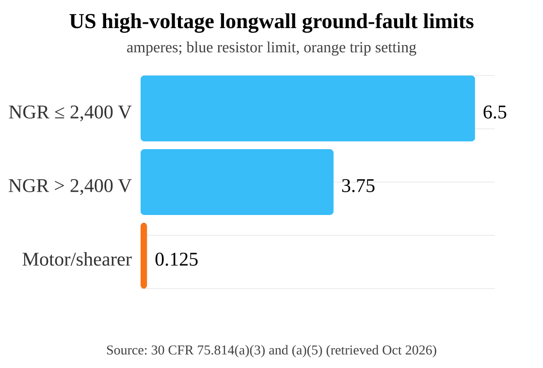
Limits for US high-voltage longwalls only, under 30 CFR 75.814(a): a neutral grounding resistor (NGR) must limit ground-fault current to 6.5 A where the circuit's nominal voltage is 2,400 V or less, and to 3.75 A above that. High-voltage motor and shearer circuits need instantaneous ground-fault protection set at not more than 0.125 A. Retrieved October 2026.
Chart data (readable on mobile):
- NGR ground-fault current limit: not more than 6.5 A when nominal circuit voltage is 2,400 V or less.
- NGR ground-fault current limit: not more than 3.75 A when nominal circuit voltage exceeds 2,400 V.
- Instantaneous ground-fault protection setting for high-voltage motor and shearer circuits: not more than 0.125 A.
These values apply only to the US high-voltage longwall circuits covered by 30 CFR 75.814. The first two are NGR current limits; the third is a protection trip setting. They are not interchangeable parameters or cable-screen current ratings.
Armour Is Not a Screen
Armour provides mechanical protection, and IEC 60502-2 gives it a clause of its own. The 2014 text lists "13 Metal armour", with subclauses on the types, materials and application of armour. That clause sits apart from clauses 7, 10 and 11 on screens and the concentric conductor. Our shielded-cable page adds that armour works as an EMI screen only when the cable design and its termination give it that job.
Our (N)3GHSSHCH mining and tunnelling cable, a flexible MV design from 3.6/6 kV up to 18/30 kV, shows the two layers side by side. Each main core is surrounded by a concentric protective conductor of copper wires or braid, and the cable also carries a monitoring conductor. It adds a galvanised steel-wire braid armour with at least 75 % coverage, which our page says cannot stand in for a protective conductor.
How to Specify Shielded Cable
Specify a shielded cable by stating the screen's job first, then the construction, data and documents that job needs. The seven checks below cover the three screening applications, mechanical armour, earthing, movement and paperwork.
- EMC screens. State the construction (braid, foil or both). Ask for Zt or screening attenuation data with the test method named, and plan the termination hardware, such as backshells or glands.
- Earthing. Agree where and how each screen is earthed with the system designer, following the guidance for that sector rather than a rule of thumb.
- MV screens. Name the metallic screen type and its cross-section, and agree the bonding method for single-core circuits with the designer.
- Mining earth screens. Confirm per-core screens, ground conductors, the ground-check conductor and the monitoring circuit. Then check the rules of the jurisdiction, such as 30 CFR or WorkSafe WA guidance.
- Armour. Specify armour for mechanical protection, and keep a separate protective conductor in the design.
- Movement duty. State whether the cable is fixed, festooned, in a drag chain, trailing or reeled. Braid design and foil affect how a screen copes with bending.
- Documents. Ask for the datasheet, the test reports behind any Zt or attenuation figure, and the standard and edition each claim refers to.
Frequently Asked Questions
Is a shielded cable the same as a screened cable?
Yes: "screen" and "shield" name the same kind of conductive or semiconductive layer. IEC documents mostly say "screen", while IEEE guides, US regulations and FAA and NASA documents say "shield". An IEC specification puts both in one phrase: "Screening (or shielding)". What matters more is the job the layer does.
Does a higher braid coverage mean a better screen?
Not on its own. Coverage is a construction value, while IEC 62153-4-3 assesses screening effectiveness through surface transfer impedance. NASA's 85 % optical coverage figure applies only to spacecraft pyrotechnic circuits. Even there, it sits alongside a minimum of 40 dB of radio-frequency attenuation from 30 kHz to 40 GHz.
Should a cable screen be earthed at one end or both ends?
It depends on the system. For spacecraft, NASA-HDBK-4001A recommends all-end termination within its near-equipotential spacecraft design. The handbook treats inner shields separately, so this is not a universal instruction to bond every nested shield to every connector backshell. FAA guidance says screened aircraft wiring is "typically connected to the aircraft's ground at both ends". Our PUR-C-HF page allows one end where the design needs it; the IEEE 1143-2012 and IEEE 575-2014 guides are inactive-reserved, with revisions under way.
Do VFD motor cables need a screen?
It depends on the drive system's EMC and earthing design. IEC 61800-3:2022 sets EMC requirements for power drive systems up to 35 kV AC RMS. The DOE tip sheet says "proper cabling and grounding practices may help reduce bearing damage". Our VFD mining cable datasheet ties the termination of its braid-and-foil screen to that design.
Why do MV cables have semiconductive layers?
Our product pages describe them as stress-control layers that manage the electric field at the conductor and insulation; our NTMCGCWÖU single-core cable, for example, has an inner and an outer one. The 2014 text of IEC 60502-2 lists separate clauses for the conductor screen and insulation screen. It also lists a normative annex on measuring the resistivity of semi-conducting screens.
Why do mining cables have a screen on each core?
In the US, regulations require it for some high-voltage cables. 30 CFR 75.804 calls for a metallic screen around each power conductor of underground high-voltage cables in "resistance grounded systems". Those cables also need ground conductors and a ground-check conductor. Section 77.804 sets a similar rule for surface high-voltage trailing cables.
Enquire About Shielded Cable
Send our engineering team the screen's job, the system voltage and the interference sources through the contact page. Add the termination method, the earthing system, the movement duty and any jurisdiction rules. Include any Zt or attenuation figures already specified, with their standard. For datasheets, browse our shielded cable range.
About the Author
Jyen is a technical and operations engineer at TEBAOFLEX, responsible for the company's online platforms. This guide draws on IEC and IEEE publication records, US federal mining regulations, Western Australian guidance, FAA, NASA and US DOE documents and TEBAOFLEX product datasheets. The product pages cited are TEBAOFLEX's own; requirements quoted from standards bodies and regulators describe their scope, not certification of our products.
Cover photo: "Coaxial cable cut", a cut coaxial cable showing its braid and foil, © FDominec, CC BY-SA 3.0, via Wikimedia Commons, cropped.
