

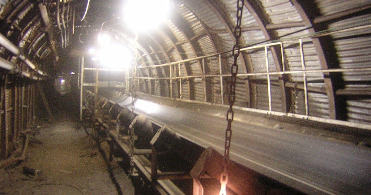
A variable frequency drive (VFD) cable carries the switched output of a drive to its motor. In a mine, the cable must also keep earth-fault protection, earthing and nearby electronics working. Australian and UK sources call the drive a variable speed drive (VSD).
The US Mine Safety and Health Administration (MSHA) lists VFDs among sources of electromagnetic interference (EMI) in underground mines in its August 2026 inspection handbook. A New South Wales (NSW) safety bulletin, SB11-04, notes that VSDs "often cause relatively large capacitively coupled currents" in the earthing systems of motors and plant.
Our VFD cable range lists conveyors, hoists, pumps, fans and crushers among drive loads. Our shielded cable guide explains cable screens.
Key Takeaways
- Standard 60 Hz ground fault systems in underground mine power centres missed faults on drives running below 10 Hz, a 2004 MSHA investigative report found.
- Pennsylvania's 25 Pa. Code §208.600 requires VSD circuits on underground coal working sections to trip at no more than 300 mA nominal. If nuisance tripping occurs, only the minimum adjustment is permitted, capped at the lower of 500 mA or half the neutral grounding resistor rating.
- Symmetrical cables feature in the May 2025 NSW code of practice, which warns that load currents above 20 A may induce voltages in the earthing conductors of non-symmetrical cables.
- Cable runs of 50 feet (about 15 m) or more from modern fast-switching drives "almost always need mitigation", according to a US Department of Energy (DOE) tip sheet.
- TU Darmstadt laboratory tests found that shielded motor cable with 360-degree terminations at both ends usually eliminates rotor ground currents; large ones may destroy bearings within months.
Where Mines Use VFDs
Mines use VFDs on belt conveyors, hoists and winders, ventilation fans, pumps and mobile machines. A 2022 National Institute for Occupational Safety and Health (NIOSH) survey included an active longwall coal mine in the eastern US. Its belt control area housed two 300 hp belt drive motors, with VFDs controlling their speed.
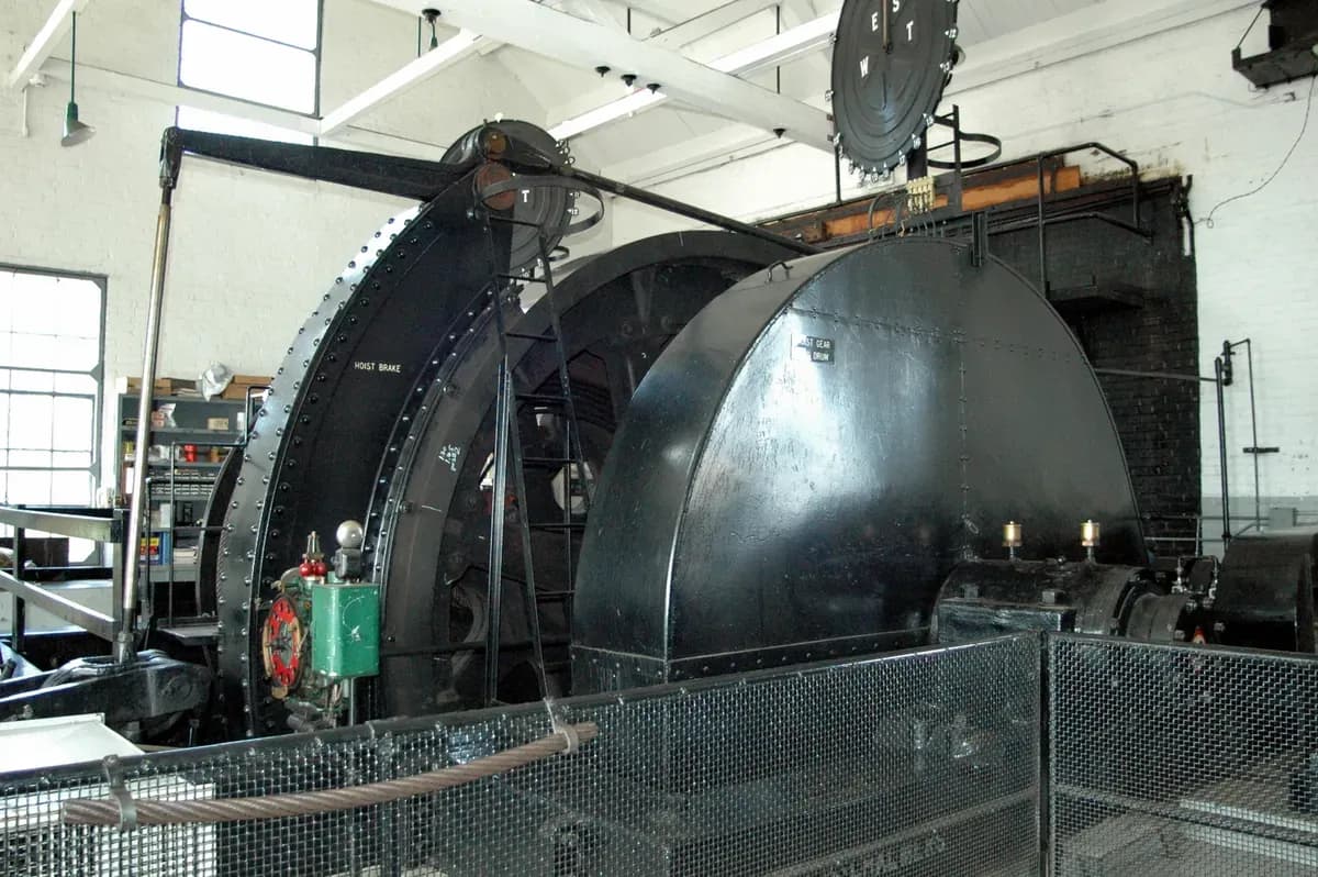
A mine hoist drum and brake preserved in a museum engine house. Photo: "Engine House - Hoist Drum" by ShakataGaNai, CC BY 3.0, via Wikimedia Commons, resized.

In 2023, an Alabama underground coal operator petitioned to modify a Code of Federal Regulations (CFR) rule, 30 CFR 75.900. The Federal Register notice records its statement that it "currently uses a circuit breaker and VFD combination out-by on conveyor belt systems".
In November 2012, a kibble winder at a non-coal mine in NSW tripped on a VSD fault while driving down to a stage. It came to a controlled stop.
A 2013 MSHA report from an Indiana underground coal mine describes a shuttle car with an on-board VFD tram system. It took 600 V DC through a trailing cable on a cable reel. NSW bulletin SB11-04 also covers VSD machines fed by reeling and trailing cables, and VSD conveyor drives and pumps powered through trailing cables.
Why VFD Cable Duty Is Different
A drive output cable carries fast pulse-width modulation (PWM) switching edges, which travel down the cable and reflect at the motor. A 2004 doctoral study at TU Darmstadt, based on laboratory tests, reports insulated-gate bipolar transistor (IGBT) rise times of typically several hundred nanoseconds. Those edges give dv/dt values of 2 to 10 kV/µs.
With rising cable length, the study found, peak voltage at the motor terminals rises up to twice the DC-link voltage. In the tests, cable type had a negligible influence on dv/dt at the motor terminals.
DOE Motor Systems Tip Sheet #15, from November 2012, says the overshoot above normal peak voltage depends on cable length and rise time. With modern IGBT switches, cable lengths of 50 feet or more "almost always need mitigation". Tip Sheet #14 adds that damaging reflected waves are generally not a problem below 15 feet (about 4.6 m) between drive and motor.
Tip Sheet #15 also warns that, on general-purpose low-voltage motors, overshoots above 1,000 V can cause a turn-to-turn short within a coil group, usually in the first couple of turns. It says carrier frequencies above 5 kHz are likely to cause bearing damage unless protective measures are taken. Both tip sheets are general industrial guidance, not mining rules.
For motors, the International Electrotechnical Commission (IEC) publishes IEC TS 60034-25:2022, an application guide for AC machines on converter supplies. IEC 60034-18-41 sets qualification and quality control tests for partial-discharge-free (Type I) insulation systems of rotating machines fed from voltage converters.
Symmetrical, Shielded VFD Cable
A common symmetrical VFD cable construction has three phase conductors with the protective earth split symmetrically between them, under an overall screen bonded at both ends. Split earth conductors are not the only symmetrical arrangement. DOE Tip Sheet #15 lists "selecting a suitable cable" among bearing-current mitigations, meaning a symmetrical design with all three phases equally spaced around the ground conductor. Our screened cable range covers other screened constructions.
The NSW code of practice on electrical engineering control plans (May 2025) lists "the use of symmetrical cables" among cable selection criteria. The aim is to minimise sparking between machines in hazardous zones and touch voltages at the machine end. Where load currents exceed 20 A, starting or normal running may induce voltages in the earthing conductors of non-symmetrical cables. The code flags rubber-tyred mobile equipment such as shuttle cars and electric boggers, which may have no other earthing.
Screens bring a trade-off. In the TU Darmstadt laboratory tests, shielded cable raised stator ground currents by up to 40% compared with unshielded cable. With 360-degree connections at both motor and inverter, it usually eliminated rotor ground currents. The study advised against pigtail grounding connections in practice, for EMI reasons.
A 2022 NIOSH paper notes that the effectiveness of cable shielding depends on proper grounding. Improper grounding, it adds, can make an EMI filter completely ineffective.
In HSG278, the UK Health and Safety Executive (HSE) lists metallic coverings for flexible cables designed to move while energised (paragraph 63). The options are flexible steel wire armour, a screen on each circuit conductor, a collective screen, or a combination. A collective screen contains an independent earth or reference conductor at least as large as the largest circuit conductor.
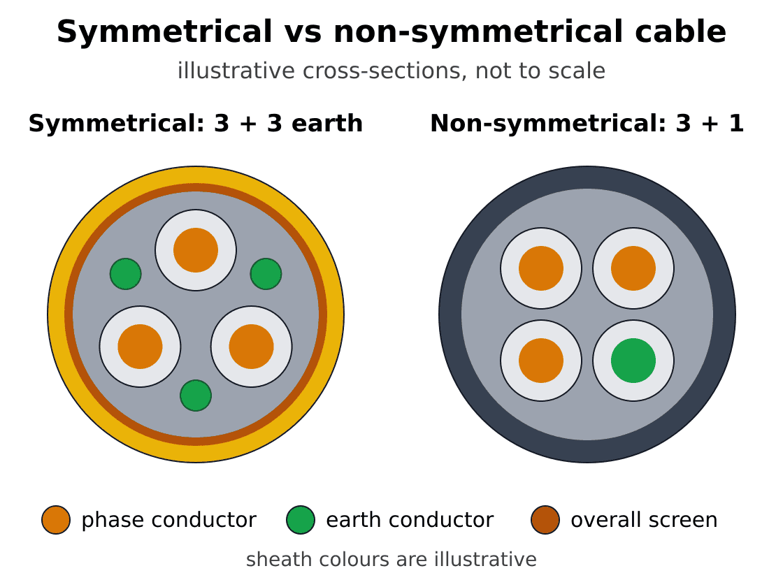
Illustrative cross-sections. Left: three phase cores with the earth split into three conductors in the gaps between them, under an overall screen. Right: three phase cores with a single earth core beside them and no screen. The NSW code notes that where load currents exceed 20 A, voltages may be induced in the earthing conductors of non-symmetrical cables. Not to scale.
Cable structure (readable on mobile):
- Left, a common symmetrical arrangement: three phase cores with three protective-earth conductors distributed between them, inside an overall screen.
- Right, the illustrated non-symmetrical arrangement: three phase cores and a single earth core alongside them, without an overall screen. This is a comparison of these two examples, not every possible cable design.
- The drawing is not to scale. A split protective earth is one symmetrical option; three phases equally spaced around a central protective earth is another.
Earth-Fault Protection on VFD Circuits
Drives can hide or imitate earth faults, so earth-fault protection needs to suit the drive's output. For neutral grounding resistor (NGR) basics, see our mine power feeder cable guide.
US Rules and the 2004 MSHA Report
In US underground coal mines, 30 CFR 75.900 requires breakers with undervoltage, grounded phase, short circuit and overcurrent protection on low- and medium-voltage three-phase circuits. Section 75.901 generally requires a grounding resistor limiting ground fault current to 25 A, and 75.902 a fail-safe ground check circuit or approved equivalent.
MSHA's 2004 report found that standard 60 Hz ground fault systems in underground power centres missed faults at one-sixth speed and below, under 10 Hz. MSHA tested a 480 V fan drive at its training academy. The power centre relay tripped above 10 Hz but not below, while the drive shut itself down on every applied fault.
The report put grounding conductor current from some drive designs as high as 480 mA, as measured by one maker on its 2,300 V drive. A 2,300 V, 500 hp drive from that maker showed an inherent current of about 18 mA at all listed speeds. Ground fault relays have tripped without nuisance at as little as 7 to 10 mA, it notes.
Because these currents can be lethal, the report recommended safeguards for underground mines. Drives adding over 125 mA to the grounding conductor should not be permitted.
VFD circuits should be limited to 500 mA of ground fault current, tripping at no more than 40% of the maximum available fault current or 125 mA, whichever is less. Interrupters should clear faults in under 125 milliseconds. These three limits should apply at all drive speeds. Ground wire monitors should hold frames to 40 V or less external to the NGR during faults.
Pennsylvania's 25 Pa. Code §208.600 requires VSD circuits on underground coal working sections, inby the last open crosscut, to trip instantly at no more than 300 mA nominal. If nuisance tripping occurs, settings may be raised to the minimum that stops it, but never above the lower of 500 mA or half the NGR current rating. The chart compares these values.
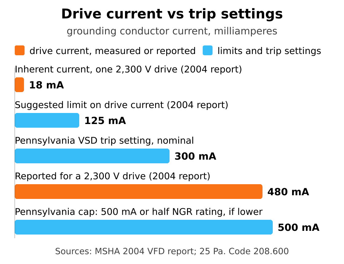
Grounding conductor current from VFDs against limits and trip settings, in milliamperes. MSHA's 2004 investigative report on VFDs gives about 18 mA inherent on one 2,300 V, 500 hp drive, and up to 480 mA reported for a 2,300 V drive. It suggests a 125 mA limit for underground mines (a recommendation, not a rule). Pennsylvania's sensitive ground fault rule (25 Pa. Code 208.600) covers VSD circuits on underground coal working sections, inby the last open crosscut. It sets 300 mA nominal, adjustable to stop nuisance tripping but never above the lower of 500 mA or half the NGR rating. The 25 A federal NGR limit for underground coal is far off this scale.
Chart data (readable on mobile):
- 18 mA: inherent current on one 2,300 V, 500 hp drive in the 2004 MSHA report; not a universal value.
- 125 mA: the 2004 MSHA report’s suggested limit on drive-added grounding-conductor current for underground mines; a recommendation, not a regulation.
- 300 mA: nominal maximum trip setting under Pennsylvania 25 Pa. Code 208.600 for the specified underground coal working-section circuits.
- 480 mA: grounding-conductor current reported by one manufacturer for a 2,300 V drive; not a trip setting.
- 500 mA: an absolute ceiling for the Pennsylvania nuisance-trip adjustment, not an automatic permitted setting. Use only the minimum necessary adjustment, never above the lower of 500 mA or half the NGR current rating.
- These values describe different measurements, recommendations and jurisdiction-specific requirements. They are not interchangeable universal protection settings.
Australia and the UK
Australian sources call the NGR a neutral earthing resistor (NER). SB11-04, issued on 21 December 2011, warns that VSDs with EMI mitigation may, in certain circumstances, weaken earth fault current limitation underground. The effect appears stronger when two or more VSD machines with EMI filters share one transformer with an NER.
Incident investigations found high-frequency earth currents significantly higher than the NER limit. Modelling suggests that currents of several times the limiting device's maximum can flow at the substation NER. On the equipment tested so far, an EMI filter fuse cleared these faults in about 1 ms; other drives should be modelled.
The bulletin notes that earth continuity relays normally trip at 45 ohms and calls for machine cable earthing resistance as low as practical. Earth leakage units on equipment fed by reeling or trailing cables should act instantaneously, with no intentional time delay. Reeling and trailing cables should be as short as possible, and all VSD-fed cables should have effective mechanical protection.
The May 2025 NSW code notes that some inverter supplies lack pure sinusoidal waveforms. A residual current device (RCD) designed for a pure AC waveform may then not operate at its intended residual current, or at all. The code says earth leakage protection on earth fault current limited networks should have at least a 10 to 1 tripping ratio against the limitation current.
In the UK, HSG278 paragraph 111 covers semiconducting, low-conductivity screens. Where they are used, the earth leakage trip setting should allow for their low conductivity and be less than 1 A.
Stored Energy and Safe Work
Capacitors in drives and power centres can stay charged after a circuit is isolated. In its safeguards for testing substations, MSHA's inspection handbook warns that high-voltage capacitors can store a lethal charge. They normally have resistors that bleed it off in about five minutes; the handbook then calls for grounding the terminals.
For US 2,400 V continuous mining machines, 30 CFR 75.825(h) requires power centres to carry a grounding stick to discharge high-voltage capacitors before electrical work. Section 75.831(d)(4) requires a qualified person to discharge all high-voltage capacitors and circuits before work inside a power centre compartment, except when troubleshooting or testing energised low- and medium-voltage circuits.
MSHA bulletin P11-52 warns that, on some battery-powered machines with two-pole plugs, drive controller capacitors can leave voltage on the exposed centre pin of a disconnected plug. It recommends opening the machine breaker before withdrawing the plug, a warning tag and task training.
UK guidance in HSG278 (paragraph 129) says isolation procedures should provide for discharging stored energy, such as in capacitors. Peru's DS 024-2016-EM, Article 350, requires a residual energy verification test before any work on equipment.
A 2020 MSHA fatality report from a Texas surface mine involved a 480 V mill line VFD that showed an overcurrent fault and would not start. MSHA's stated cause was that the operator did not ensure adequate phase lead connections, or proper personal protective equipment for troubleshooting energised equipment.
Standards for VFD Mining Cable
Mining VFD cable draws on cable product standards, US approval rules, drive standards and national mining standards. For DIN VDE cable types, see our DIN VDE cable standards page.
- CSA Group, the Canadian standards body, publishes CSA C22.2 No. 96:23 for portable power cables. Its Clause 14 covers round multiconductor VFD cable for mining and general use, rated 2 kV to 15 kV (Types VFD, VFD-GC and VFD-BGC).
- DIN VDE 0250-812:1985 is the current standard for rubber-insulated flexible cable type NSSHÖU. Our (N)SSHCÖU design is based on it; this is a design basis, not a conformity claim.
- 30 CFR 18.47(d)(4) and (5) are MSHA approval rules for permissible machines. From 661 to 4,160 V, trailing cables need grounding conductors, a ground check conductor and grounded metallic shields, one per power conductor above 1,000 V. Reel machines up to 1,000 V may use unshielded cable insulated for 2,000 V or more.
- Drive standards include IEC 61800-5-1:2022 for safety and IEC 61800-3:2022 for electromagnetic compatibility (EMC). The Institute of Electrical and Electronics Engineers (IEEE) lists IEEE 519-2022, on harmonic control, as active, and IEEE 1566-2015, on petrochemical AC drives above 375 kW, as Inactive-Reserved.
- AS/NZS 5368:2025, on electrical equipment in mines and quarries, superseded AS/NZS 3007:2013 and the AS/NZS 4871 series. The May 2025 NSW code still names AS/NZS 3007, and SB11-04 cites AS/NZS 4871.1 Appendix E.
Our VFD Mining Cable Designs
Our two VFD mining designs are the (N)SSHCÖU VFD mining cable for 0.6/1 kV and the 2 kV VFD mining power cable. The table summarises what their datasheets list.
- Feature: Construction — (N)SSHCÖU 0.6/1 kV: Three class 5 tinned copper power cores; also listed for 640/1140 V — VFD mining power cable, 2 kV: Three tinned, rope-stranded, extra-flexible power conductors; 2,000 V rating
- Feature: Earth and ground check — (N)SSHCÖU 0.6/1 kV: Earth divided into three parts in the outer interstices — VFD mining power cable, 2 kV: Three green insulated grounding conductors plus a yellow ground-check conductor
- Feature: Screen — (N)SSHCÖU 0.6/1 kV: Concentric tinned copper braid designed for EMC — VFD mining power cable, 2 kV: Tinned copper braid and aluminium/polyester tape; 100% coverage
- Feature: Insulation and sheath — (N)SSHCÖU 0.6/1 kV: Ethylene propylene rubber (EPR, 3GI3) insulation, EPR inner sheath, 5GM5 elastomer outer sheath — VFD mining power cable, 2 kV: Type II EPR insulation; reinforced thermoset chlorinated polyethylene (CPE) jacket
- Feature: Temperatures — (N)SSHCÖU 0.6/1 kV: Conductor 90 °C, short circuit 250 °C; ambient minus 40 °C fixed, minus 25 °C flexing ((N)SSHCÖU (-45 °C) cold-version datasheet: minus 60 °C fixed, minus 45 °C flexing) — VFD mining power cable, 2 kV: Conductor 90 °C continuous
- Feature: Sizes and current examples — (N)SSHCÖU 0.6/1 kV: 3×16+3×2.5 to 3×240+3×120/3 mm²; 99 to 540 A laid on a surface at 30 °C (301 A for 3×95+3×50/3) — VFD mining power cable, 2 kV: 2 American Wire Gauge (AWG) to 500 kcmil; 159 to 536 A at 40 °C ambient (321 A for 4/0 AWG)
- Feature: Capacitance — (N)SSHCÖU 0.6/1 kV: 0.42 to 0.73 µF/km — VFD mining power cable, 2 kV: Not listed
- Feature: Design reference — (N)SSHCÖU 0.6/1 kV: DIN VDE 0250 part 812 (design basis) — VFD mining power cable, 2 kV: Insulated Cable Engineers Association (ICEA) S-75-381 / NEMA WC 58 (primary reference)
Our pages and datasheets are design references, not approval or conformity certificates. The approval each jurisdiction requires is confirmed per order.
How to Specify a Mine VFD Cable
Specify a mine VFD cable from the drive and motor data outwards, then confirm earthing, screening, duty and local rules. Our mining and tunnelling range covers related mine cables.
- Drive and motor data. Record voltage, power, carrier frequency and the drive maker's maximum lead length.
- Route length. At 50 feet or more, DOE guidance says mitigation is almost always needed; ask whether filters are required.
- Symmetrical construction. Specify a symmetrical phase and protective-earth arrangement suited to the drive, such as three symmetrically distributed earth conductors, and check the total earth area.
- Screen. Confirm screen type and coverage, with 360-degree terminations at both ends.
- Earth-fault protection. Plan the ground check circuit and confirm relay response at low drive frequencies.
- Mechanical duty. State fixed, flexing, trailing or reeling duty; see our shearer and continuous miner cable guide. Our 2 kV datasheet lists reel correction factors of 0.85, 0.65, 0.45 and 0.35 for one to four layers. Our load-haul-dump (LHD) and jumbo cable guide compares them with the lower static factors of a 1994 shuttle car reel model.
- Environment. Note cold, water, oil and sunlight, and match sheath and temperature ratings.
- Separation and stored energy. Chile's DS 132, Article 418, requires communication cables to run far enough from power or high-voltage cables. Add capacitor discharge to isolation procedures.
Frequently Asked Questions
Do mine VFDs need shielded cable?
NSW guidance points to shielded cable on VFD circuits, because drives are EMI sources and cause capacitive earth currents. The NSW code lists the sheaths of VSD-fed cables that are not effectively shielded as a hazard example. For any flexible cable designed to move while energised, HSG278 lists flexible armour, individual screens or a collective screen as metallic coverings.
Why can a VFD hide a ground fault?
Earth-fault relays built for supply frequency may not detect faults at low drive output frequencies. MSHA's 2004 report found that underground power centre relays missed ground faults below 10 Hz, or one-sixth speed. NSW bulletin SB11-04 adds that, in some cases, VSDs with EMI filters may weaken earth fault current limitation.
How long can a VFD motor cable be?
Maximum length depends on the drive maker's permitted lead length. With modern IGBT switches, DOE Tip Sheet #15 says runs of 50 feet (about 15 m) or more almost always need mitigation. Below 15 feet (about 4.6 m), Tip Sheet #14 says damaging reflected waves are generally not a problem.
What is a symmetrical VFD cable?
One common symmetrical VFD cable design splits the protective earth into equal parts placed symmetrically between the three phase conductors. Other symmetrical arrangements include three phases equally spaced around a central protective earth conductor. The NSW code warns that with load currents above 20 A, voltages may be induced in the earthing conductors of non-symmetrical cables.
Which standard covers VFD mining cable?
CSA C22.2 No. 96:23 covers VFD mining cable directly, in Clause 14, for ratings of 2 kV to 15 kV. IEC 61800-3:2022 and AS/NZS 5368:2025 also bear on drive installations in mines. Our special cables guide covers other cable standards.
How should a VFD cable shield be terminated?
A VFD cable shield should be terminated with 360-degree connections at both drive and motor. In laboratory tests, shielded cable so connected usually eliminated rotor ground currents; pigtails were not recommended, for EMI reasons. Chile's DS 132, Article 467, requires couplings that secure screened or armoured conductors entering metal housings and bond the screen or armour to the housing.
Enquire About Mine VFD Cable
To quote a mine VFD cable, our engineering team needs the drive and motor data, carrier frequency, route length and conductor size. Please also give earth and ground-check needs, the screen termination plan, fixed or moving duty, ambient conditions and the standard your jurisdiction requires. Send these through our contact page.
About the Author
Jyen is a technical and operations engineer at TEBAOFLEX, responsible for the company's online platforms. This guide draws on US federal and Pennsylvania mine safety rules, MSHA reports and guidance, DOE tip sheets, and NIOSH and university research. It also uses New South Wales and UK regulator guidance, Chilean and Peruvian mining regulations, standards catalogue records and TEBAOFLEX product datasheets. The product pages cited are TEBAOFLEX's own; requirements quoted from regulators and standards bodies describe their scope, not certification or approval of our products.
Cover photo: "Thoresby BCV" by Na derdingseben, CC BY-SA 3.0, via Wikimedia Commons, cropped.
