

Two partial discharge (PD) certificates can both say "pass" and describe very different tests. One could see any discharge above 5 picocoulombs (pC). The other could see nothing below 50 pC. A 2022 CIGRE-USNC paper, written mainly by staff of a PD testing company, put a number on that gap. A test that cannot detect a 50 pC pulse "could be missing 60% of PD activity" that a test with verifiable 5 to 10 pC sensitivity would find.
For buyers of medium-voltage (MV) trailing and reeling cables, the problem often starts in the specification. Specs paste in "IEC 60502-2, PD ≤ 10 pC" for cables that standard excludes. Reports then arrive with a pC figure but no test voltage and no sensitivity.
This guide covers which standard sets the PD limit, and how to work out the test voltage from the cable rating. It also lists what to check on a PD report and explains why site results differ from factory ones. For type, routine and repair tests in general, see our mining cable testing guide.
Key Takeaways
- IEC 60502-2 excludes cables for "the mining industry". A mining cable's PD limit must come from its own standard or be written into the order.
- A pC limit means little without a test voltage. In the 2005 text of IEC 60502-2's routine test, the PD reading is taken at 1.73 U0 after 10 s at 2 U0. For a 12/20 kV cable, 1.73 U0 works out at about 20.8 kV.
- The declared sensitivity decides what "no discharge" means: IEC 60502-2's 2005 routine test asks for 10 pC or better. The public 2009 text now catalogued as China's KA/T 818.6 (formerly MT/T 818.6) sets 20 pC or less at 1.73 U0 for mobile metal-screened monitoring flexible cables in coal mines, up to 8.7/10 kV.
- Installed systems fail at their accessories as well as in the cable. Joints and terminations caused 34% of high-voltage land cable faults in a CIGRE survey and an estimated 42.7% of North American MV failures.
What a PD Test Shows on a Mining Cable
A PD test finds small discharges inside the insulation system before they grow into a breakdown. It is a quality check on a length of cable, not a prediction of its life.
Partial discharges bridge only part of the insulation between conductor and earth. They start in gas-filled voids, around contaminants, or where a semiconductive screen has come away from the insulation. Each discharge moves a tiny charge. Instruments measure it as apparent charge in pC, following IEC 60270:2025, "Charge-based measurement of partial discharges", now in its fourth edition.
For cable, IEC 60885-3 gives PD test methods for "lengths of extruded power cable". It "does not include measurements made on installed cable systems". That split between a drum length and an installed system runs through this whole guide.
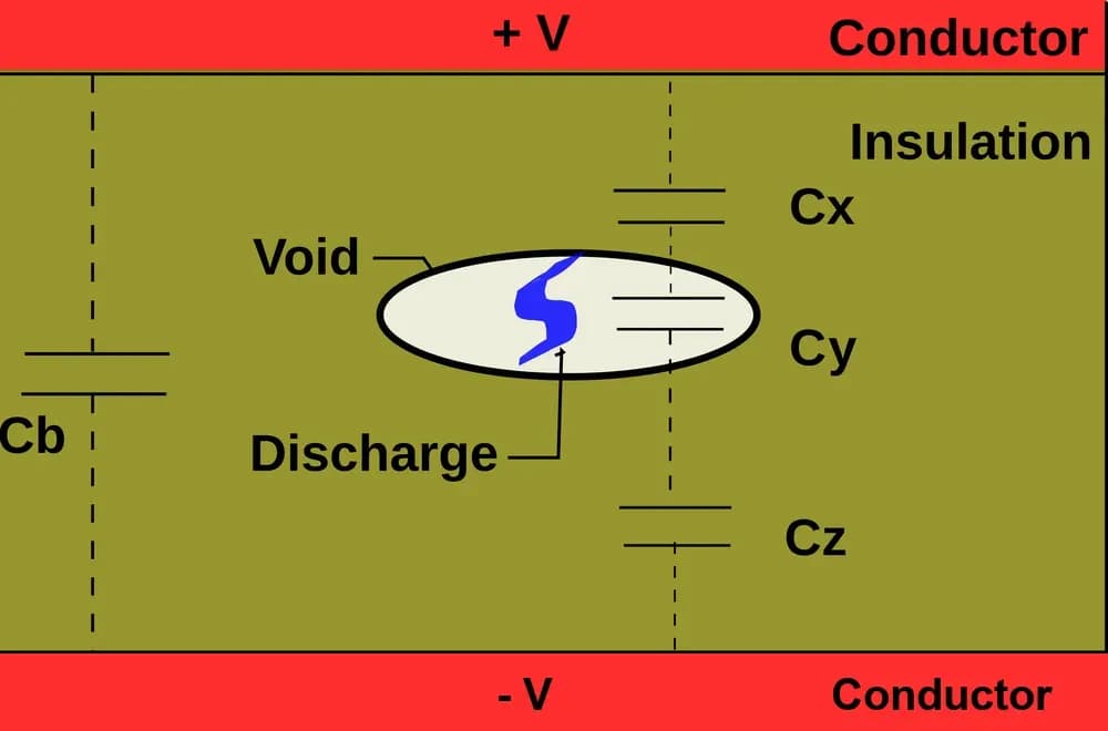
A discharge inside a void in solid insulation. The void and the healthy insulation act as capacitors in series, so a discharge in the void shows up as a small charge pulse at the cable ends. Diagram: "Partial discharge.svg" by Wtshymanski, CC BY-SA 3.0, via Wikimedia Commons, rendered, with the clipped bottom label redrawn.

MV trailing and reeling cables add their own risks. Most use ethylene propylene rubber (EPR) insulation on a finely stranded flexible conductor. The insulation sits between a semiconductive conductor screen and a semiconductive insulation screen. Those screens smooth the electric field. Where a screen is missing, damaged or not bonded to the insulation, the field concentrates and PD can start.
A PD result is evidence, not a verdict. The Cable Diagnostic Focused Initiative (CDFI), co-funded by the US Department of Energy and run by the National Electric Energy Testing, Research and Applications Center (NEETRAC), pooled 18 data sets covering 669 miles of utility cable. In its 2010 final report, PD techniques reached a weighted median overall accuracy of 79.5%.
Segments diagnosed "Pass" rarely failed. Yet "fewer than 1 in 20 Not Pass segments actually go on to fail within several years of testing". Those were utility systems, not mining cables, but the lesson carries: read a PD result as a guide to where to look.
Which Standard Sets the PD Limit?
China's current national catalogue lists KA/T 818.6-2009 as replacing MT/T 818.6-2009. Item 291 of the 2026 transfer notice records this change of designation. The 20 pC requirement at 1.73 U0 and the type/routine markings quoted below are from the publicly available 2009 text under the former MT/T number. Confirm the governing text and edition in the order; the catalogue entry is not a product certification.
IEC 60502-2 does not cover mining cables, so the PD limit must come from the mining cable standard on the order or be agreed for that order. Its catalogue scope lists "the mining industry" among the special service conditions it leaves out.
Buyers still borrow its routine PD test because it is clear and widely known. That works if the order says the method is borrowed by agreement. It causes trouble when a spec cites IEC 60502-2 as if it governed the cable.
Mining cable standards use two different kinds of PD criterion:
- Charge at a fixed voltage. The cable must show no more than a set charge at a set voltage. IEC 60502-2 works this way, and so does China's KA/T 818.6-2009. Clause 4.9.2 of KA/T 818.6 requires a PD test at 1.73 U0 with a discharge of no more than 20 pC. Its test table marks the PD test as "T,R", the usual Chinese notation for a type and routine test.
- Extinction voltage. Here the voltage at which PD stops, as the test voltage is lowered, must not fall below a set level. The contents list of ANSI/NEMA WC 58-2017 / ICEA S-75-381-2017 shows this approach. That standard covers portable and power feeder cables for mines, with mine power cables from 2,001 to 25,000 V. It includes Table 4-6, "Partial Discharge Extinction Voltage", and a test procedure in section 6.17.3.
A specification such as "≤ 10 pC to ICEA S-75-381" needs clarification: state the applicable clause, test voltage and sensitivity, and whether acceptance is based on charge, extinction voltage or both. The table below gives numbers only where we could read them in a public source.
- Standard: IEC 60502-2; Scope: Extruded power cables, 6 to 30 kV; excludes mining; How PD is judged: Charge at a fixed voltage (routine and type); Voltage and limit: 1.73 U0 after 2 U0 for 10 s; no detectable discharge above the declared sensitivity (routine: 10 pC or better); Public text checked: Yes, 2005 text; current edition 2014+AMD1:2024
- Standard: KA/T 818.6-2009 (formerly MT/T 818.6-2009); Scope: Mobile metal-screened monitoring flexible cables for coal mines, 3.6/6 to 8.7/10 kV; How PD is judged: Charge at a fixed voltage (type and routine); Voltage and limit: 1.73 U0; 20 pC or less; Public text checked: Yes, public 2009 text under the former MT/T number; current KA/T catalogue relationship verified
- Standard: ICEA S-75-381 / NEMA WC 58; Scope: Portable and power feeder cables for mines; How PD is judged: Extinction voltage (Table 4-6); Voltage and limit: See standard; Public text checked: Clause titles only
- Standard: AS/NZS 1802:2018; Scope: Reeling and trailing cables, underground coal mines; How PD is judged: See standard; Voltage and limit: See standard; Public text checked: No
- Standard: AS/NZS 2802:2000; Scope: Reeling and trailing cables, mining other than underground coal; How PD is judged: See standard; Voltage and limit: See standard; Public text checked: No
- Standard: DIN VDE 0250-813; Scope: Trailing cables (Leitungstrosse); check the applicable cable construction; How PD is judged: See standard; Voltage and limit: See standard; Public text checked: No
- Standard: IEEE 400.3-2022; Scope: Field PD tests on installed shielded systems; How PD is judged: Guide, no pass/fail limit; Voltage and limit: —; Public text checked: Yes
Where a row reads "see standard", buy the current edition and copy its PD clause into the order. Do not rely on a figure quoted on a supplier's website, including ours.
Test Voltage: What 1.73 U0 and 2 U0 Mean
A pC limit without a test voltage cannot be checked, because the PD response depends on the applied voltage and test conditions. PD test voltages are given as multiples of U0, the rated voltage between each conductor and its screen or earth. A 12/20 kV cable has U0 = 12 kV and a phase-to-phase rating U of 20 kV.
The public 2005 routine PD clause of IEC 60502-2 illustrates the sequence. Its second edition (2005) was adopted as technically identical in COMESA 227-2:2006, a regional standard whose text can be read on the Internet Archive. In clause 16.3, the voltage is "raised gradually to and held at 2 U0 for 10 s and then slowly reduced to 1,73 U0". For three-core cables, every insulated core is tested, with voltage applied between each conductor and its screen. The 2014 edition numbers the routine PD test 16.3. The current catalogue record is IEC 60502-2:2014+AMD1:2024 (Edition 3.1), with the July 2026 correction incorporated. The complete current clause has not been verified for this guide; check the edition specified in the order before using the 2005 example as a test requirement.
Worked example: for 12/20 kV, 1.73 × 12 kV gives about 20.8 kV, and 2 × 12 kV gives 24 kV. The table applies the same arithmetic to common mining ratings. These values are calculated from U0, not quoted from any standard.
- Rating U0/U: 3.6/6 kV; U0: 3.6 kV; 1.73 U0 (PD measured): 6.2 kV; 2 U0 (10 s pre-stress): 7.2 kV
- Rating U0/U: 6/10 kV; U0: 6 kV; 1.73 U0 (PD measured): 10.4 kV; 2 U0 (10 s pre-stress): 12 kV
- Rating U0/U: 8.7/15 kV; U0: 8.7 kV; 1.73 U0 (PD measured): 15.1 kV; 2 U0 (10 s pre-stress): 17.4 kV
- Rating U0/U: 12/20 kV; U0: 12 kV; 1.73 U0 (PD measured): 20.8 kV; 2 U0 (10 s pre-stress): 24 kV
- Rating U0/U: 18/30 kV; U0: 18 kV; 1.73 U0 (PD measured): 31.1 kV; 2 U0 (10 s pre-stress): 36 kV

PD measurement voltage at 1.73 U0, calculated from U0: 6.2 kV for 3.6/6 kV, 10.4 kV for 6/10 kV, 15.1 kV for 8.7/15 kV, 20.8 kV for 12/20 kV and 31.1 kV for 18/30 kV. These are arithmetic, not values from a standard; the governing standard and the order set the actual test voltage.
PD test voltage at 1.73 U0 by rating (text version)
- 3.6/6 kV: 1.73 U0 = 6.2 kV (calculated)
- 6/10 kV: 1.73 U0 = 10.4 kV (calculated)
- 8.7/15 kV: 1.73 U0 = 15.1 kV (calculated)
- 12/20 kV: 1.73 U0 = 20.8 kV (calculated)
- 18/30 kV: 1.73 U0 = 31.1 kV (calculated)
Do not confuse the PD voltage with the alternating current (AC) withstand voltage. Our 12/20 kV excavator cable case reports an AC test at 29 kV for 5 minutes, with no breakdown. That withstand test proves the insulation survives a high voltage. It is not the voltage at which the PD reading was taken.
Sensitivity and Background Noise: The Line Buyers Skip
The declared sensitivity is the smallest discharge the test could have seen. "No PD detected" at 50 pC sensitivity is a different result from the same words at 5 pC.
IEC 60502-2 builds this into its pass criterion. Under the 2005 routine clause, the sensitivity "shall be 10 pC or better". The cable passes if there is "no detectable discharge exceeding the declared sensitivity from the test object at 1,73 U0". The type test asks for 5 pC or better. That is why the method caps sensitivity: a test coarser than the required value does not meet this criterion, even if it detects no PD.
The 2015 edition of IEC 60885-3 tightened how sensitivity is judged. It removed the old definition of sensitivity "as twice the background noise level". In its place is "a practical assessment of sensitivity based on the minimum level of detectable discharge". It also replaced pulse heights in millimetres on an oscilloscope with PD magnitude in pC.
Before measuring, a calibrator injects a known charge at the cable end so that the detector reading can be scaled to pC. On our PD detector, the calibration output dial runs from 2 to 400 pC, with Cq = 100 pF. A report should give the calibrator charge used, the background noise and the sensitivity that results.

Our PD detector panel, with its calibration output dial set in pC (2 to 400 pC, Cq = 100 pF). Meter readings are blurred and the instrument maker's name is cropped out. Photo: TEBAOFLEX.

Share of PD activity missed compared with a test of verifiable 5 to 10 pC sensitivity: about 60% for a test that cannot detect 50 pC, and over 80% for a test with only 100 pC sensitivity. From a database of over 250,000 field PD tests on 5 to 500 kV cable systems. Three of the paper's five authors work for IMCORP, a PD testing company; the data are utility cable systems, not mining cables.
PD activity missed at coarse sensitivity (text version)
- Verified 5 to 10 pC sensitivity: Reference test, not a universal mining-cable limit.
- 50 pC sensitivity: About 60% of PD activity could be missed relative to the reference.
- 100 pC sensitivity: Over 80% of PD activity could be missed relative to the reference.
The same database covers 17 countries and 49 US states. In it, calibrated sensitivity of 5 to 10 pC was reached "in over 95% of cases". If field tests can reach that level, a factory PD report should be able to state its own figure.
How to Read a PD Test Report, Line by Line
Check ten fields on every PD report. If the voltage, sensitivity or per-core result is missing, ask for it before accepting the drum.
- Cable and length: designation, drum number and length tested.
- Standard and clause: the document and clause the test follows.
- Rating: U0/U, so the test voltage can be checked.
- Voltage steps: pre-stress level and time, then the measuring voltage.
- Calibrator charge: the known charge injected before the test.
- Noise and sensitivity: background noise and the declared sensitivity, in pC.
- Result per core: PD in pC at the stated voltage, for each core.
- PDIV and PDEV: the PD inception voltage and extinction voltage, when reported.
- Pattern or location: a phase-resolved PD (PRPD) pattern or a location, when reported.
- Test record: test circuit, ambient conditions, signature and any witness.
Here is the PD row from the factory acceptance test (FAT) report of our 12/20 kV order for a Polish excavator. The cable was our (N)TSCGECEWÖU flexible MV cable, 3×35+3×25/3. We have re-typed the cells. The requirement was 10 pC or less, set by the order rather than by a universal limit. The result was 2.0 with a pass mark, and the method cell names a series resonance PD test system.

The PD row of our 12/20 kV (N)TSCGECEWÖU FAT report, re-typed: requirement 10 pC or less, set by the order; method, a series resonance PD test system; result 2.0; verdict, pass. Items A to E appear on the report. Items F to J do not: test voltage, calibrator charge, noise and sensitivity, the core and drum tested, and PDIV, PDEV or PRPD.
PD row of our 12/20 kV FAT report, annotated (text version)
- A — On the report: Item: names the test, nothing more.
- B — On the report: Requirement: the order's limit, with no voltage stated.
- C — On the report: Method: names the test system, not the voltage steps.
- D — On the report: Result: 2.0, with no unit in the cell; pC is implied.
- E — On the report: Verdict: a pass mark, which needs F to J to mean much.
- F — Not on the report: Test voltage, e.g. 1.73 U0 ≈ 20.8 kV (calculated) for 12/20 kV.
- G — Not on the report: Calibrator charge injected before the measurement.
- H — Not on the report: Background noise and declared sensitivity, in pC.
- I — Not on the report: Core and drum tested (the order had 500 m and 480 m lengths).
- J — Not on the report: PDIV and PDEV, or a PRPD pattern, if measured.
What the row leaves out matters as much. It gives no test voltage, no calibrator charge and no noise level or sensitivity. It does not say which core or which drum was measured, though the order covered a 500 m and a 480 m length. We show our own report because its gaps are exactly the fields a buyer should write into the order.
Where PD Starts in Flexible Rubber Mining Cables
In trailing and reeling cables, the likely PD sites are screen interfaces and terminations. Flexing, crushing and cold bending can create new sites after the cable leaves the factory.
Screens on flexible conductors. The conductor screen and insulation screen must stay in close contact with the EPR insulation as the cable bends. A gap at either interface is where discharges tend to begin. Our guide to semiconductive and metallic screens explains how those layers are built.
Reeling, drag and pinch points. Cables on bucket-wheel excavator reels see repeated bending under tension. Shovel and dragline trailing cables are dragged, run over and pinched. A crush can lift a screen or deform the insulation. A factory PD result cannot show damage done after delivery.
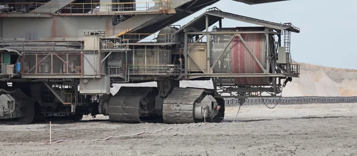
A reeling drum on spreader 761 in a German open-cut mine, with its red power cable paid out across the ground. Every metre on the reel is bent and straightened as the machine moves. Photo by Smokeyharry, CC BY-SA 4.0, via Wikimedia Commons, cropped and resized.

Terminations. Where a cable is terminated, the semiconductive screen must be cut back cleanly and kept clear of live parts. Queensland's mines safety alert no. 329 (August 2016) describes two failures. At a surface coal mine, 6,600 V cables with a semiconductive outer screen were left touching exposed terminals. That caused a phase-to-phase fault and an arc blast that blew a door off its hinges. At an 11,000 V isolator, semiconductive insulation was left touching the termination lugs.
The alert notes that earthed semiconductive screens near terminations help "prevent ionisation and partial discharge (PD)". It recommends that electrical tradespeople understand how conductive these screens are, and that they keep proper creepage and clearance distances. The alert is about work practice, not PD testing. It still shows why a site PD test covers the terminations as well as the cable.
Factory vs Site: Why the Numbers Differ
A factory test measures one drum length, with its ends in test terminations, in a controlled room. A site test measures the installed system, including terminations, couplers and splices, in an electrically noisy plant. A higher site reading does not, by itself, mean the cable body is defective.
At our factory, when an order specifies a PD test, the drum is tested in a metal-clad test room. In the photo below, a core end is taken into a liquid-filled test termination. Terminations like this are used so that the test end does not discharge and mask the cable itself.

A red MV flexible cable on its drum during a factory PD test in our metal-clad test room. One core end sits in a liquid-filled test termination; the high-voltage test set stands at the right. Photo: TEBAOFLEX.
Field data show where installed systems fail. CIGRE Technical Brochure (TB) 815 surveyed land cable systems at 60 kV and above from 2006 to 2015. Of 744 faults, 56% were in the cable, 16% in joints, 18% in terminations and 9% in other components.
The CDFI's estimate for North American MV systems, based on 2006 and 2007 utility surveys, puts 56.2% of failures in cable, 37.1% in splices and 5.6% in terminations. Neither population is mining, but both point the same way. Accessories account for a third or more of failures.
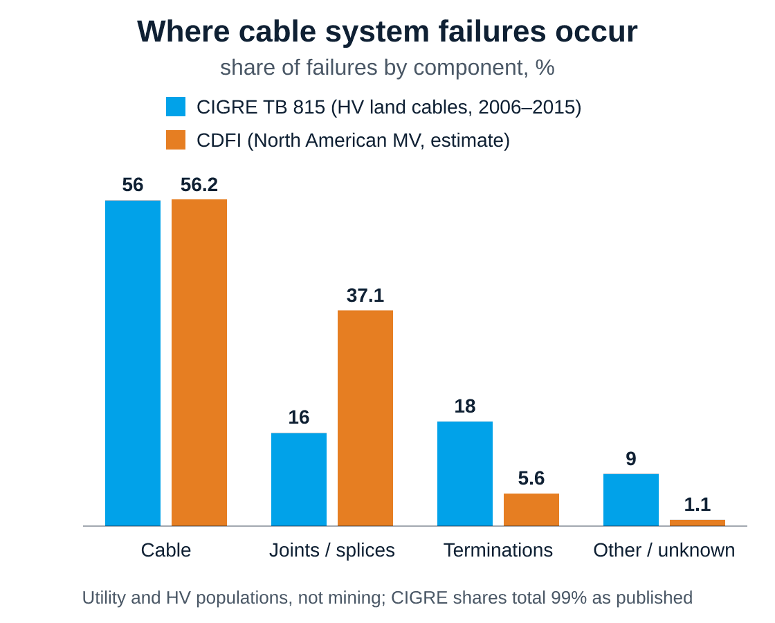
Share of cable system failures by component. CIGRE TB 815 (744 faults on land cables at 60 kV and above, 2006 to 2015): cable 56%, joints 16%, terminations 18%, other 9%. CDFI estimate for North American MV systems (utility surveys, 2006 to 2007): cable 56.2%, splices 37.1%, terminations 5.6%, unknown 1.1%. Neither population is mining cable.
Where cable system failures occur (text version)
- Cable: CIGRE HV land survey: 56%; CDFI North American MV estimate: 56.2%.
- Joints / splices: CIGRE: 16%; CDFI: 37.1%.
- Terminations: CIGRE: 18%; CDFI: 5.6%.
- Other / unknown: CIGRE: 9%; CDFI: 1.1%. CIGRE shares total 99% as published.
New systems show the same pattern. The CIGRE-USNC paper reports that 37.1% of new 5 to 500 kV cable systems did not pass a factory-comparable PD test, meaning a field test with factory-level sensitivity. That 37.1% is unrelated to the CDFI's 37.1% splice share above. By component, 3.0% of terminations, 4.4% of joints and 1.6% of cables did not pass. The paper's Table I lists accessory criteria as well: no PD above 5 pC up to 1.5 U0 for terminations to IEEE 48 and joints to IEEE 404, and up to 1.3 U0 for separable connectors to IEEE 386.
Noise is the other difference. Shovels, draglines and bucket-wheel excavators run large drives whose switching produces high-frequency interference, which a PD detector can mistake for discharges. Our article on VFD noise on mine drives covers where it comes from.
For site testing, IEEE 400.3-2022 is a guide for "partial discharge field diagnostic testing of shielded power cable systems", covering cable, joints and terminations. It does not set a pass/fail limit, so the site criterion has to be agreed too.
What to Write Into the Purchase Order
State the standard and clause, the pC limit at a stated voltage, the maximum sensitivity and which cores and drums are tested. Then the PD result can be checked on paper.
- Standard and clause. Name the governing cable standard and its PD clause. If the IEC 60502-2 method is borrowed, say so as an agreed method.
- Limit and voltage. For example: "≤ X pC at 1.73 U0, after 2 U0 for 10 s". X is the buyer's choice; we do not suggest a universal number.
- Sensitivity. Declared sensitivity no coarser than the limit, checked by calibrator injection before and after the measurement.
- Scope. Every core of every drum, identified by drum number.
- Report fields. The ten checklist fields from the report-reading section, with measured values rather than pass marks.
- Witnessing. A witness option and notice period, as set out in our mining cable testing guide.
- Site baseline. A PD baseline after installation, and re-tests after splices or repairs, trended against that baseline.
Frequently Asked Questions
What pC level is acceptable for an MV mining cable?
The acceptable level depends on the governing standard and the order. The public 2009 text now catalogued as China's KA/T 818.6 (formerly MT/T 818.6) sets 20 pC or less at 1.73 U0 for mobile metal-screened monitoring flexible cables in coal mines, up to 8.7/10 kV. The public 2005 routine-test text of IEC 60502-2, which excludes mining cables, requires no detectable discharge above a declared sensitivity of 10 pC or better. Treat these as examples, not universal limits, and always state the voltage with the pC figure.
What test voltage is used for a cable PD test?
In the publicly quoted 2005 routine test of IEC 60502-2, the voltage is held at 2 U0 for 10 s, then slowly reduced to 1.73 U0, where the PD is measured. KA/T 818.6 also measures at 1.73 U0. For a 12/20 kV cable, U0 is 12 kV, so 1.73 U0 is about 20.8 kV and 2 U0 is 24 kV. These figures are calculated from U0.
What are PDIV and PDEV?
The PD inception voltage (PDIV) is the voltage at which PD first appears as the test voltage rises. The PD extinction voltage (PDEV) is the voltage at which it stops as the voltage falls. PDEV is usually lower. ICEA S-75-381 / NEMA WC 58 uses an extinction-voltage table for mine power cables, so read the standard for its values and test sensitivity.
Is PD testing required for mining trailing cables?
It depends on the cable standard and the jurisdiction. The public 2009 text now catalogued as KA/T 818.6, under the former MT/T number, lists PD as a type and routine test for the mobile metal-screened monitoring flexible cables it covers. For other standards, check the current edition. Then write the PD test, voltage and sensitivity into the order so the requirement is explicit.
Why is my site PD result higher than the factory result?
A site test sees the whole installed system: terminations, joints and couplers as well as the cable. It also runs among drives and switchgear that add noise, and the cable may have been damaged in handling or service. A higher site reading points to where to look. It does not prove the cable body is faulty. IEEE 400.3 is a guide for planning field PD tests.
Enquire About PD-Tested MV Cables
To enquire, send our engineering team the cable type and rating, the governing standard, and the PD limit with its test voltage and sensitivity. Add which cores and drums you want tested, your report format and any witness or site baseline plans. Use our contact page to enquire about PD-tested cables. Our MV reeling cable, trailing cables and wider mining and tunnelling range can be specified this way.
About the Author
Jyen is a technical and operations engineer at TEBAOFLEX, responsible for the company's online platforms. This guide draws on IEC catalogue records and the text of IEC 60502-2:2005, China's KA/T 818.6, the NEMA WC 58 contents list and IEEE standard pages. It also uses CIGRE and US Department of Energy reports, a Queensland mines safety alert, and TEBAOFLEX's own FAT report, photos and case pages. Requirements quoted from standards bodies and regulators describe their scope, not certification or approval of our products.
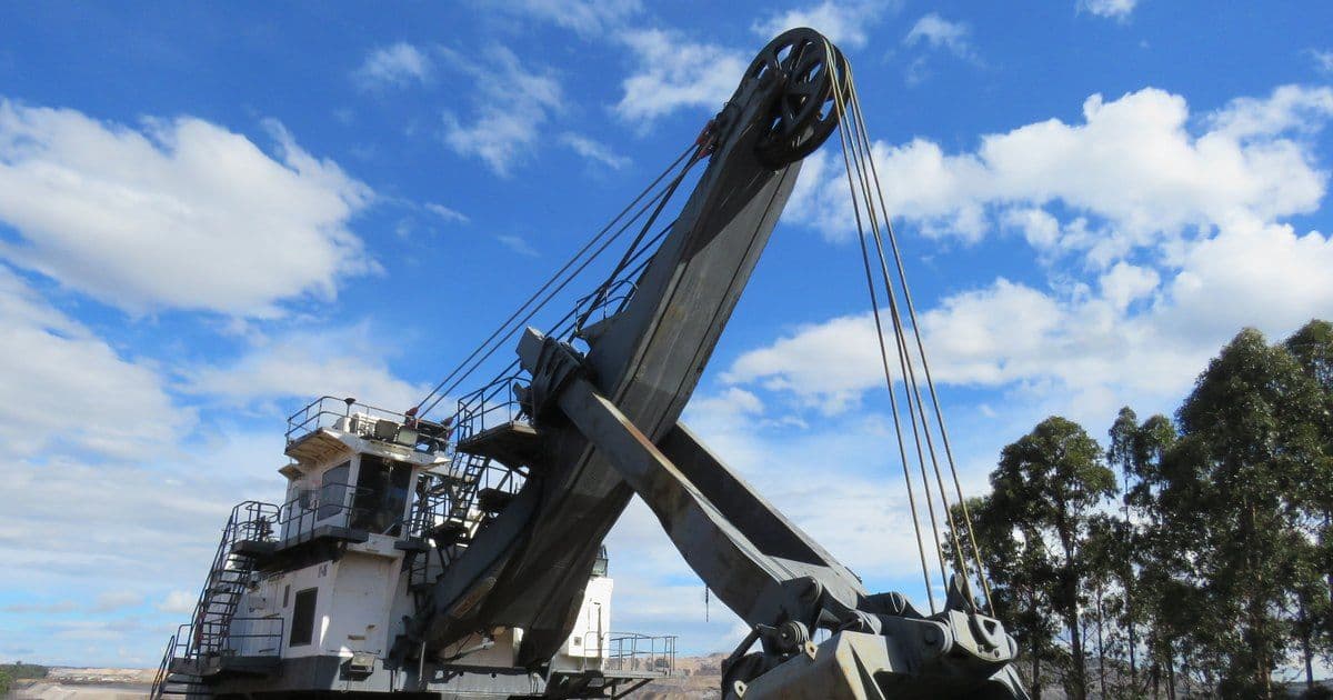
Cover photo: "Dragline excavator Shovel 6, Collie, April 2022 05" by Calistemon, CC BY-SA 4.0, via Wikimedia Commons, cropped, with signage and maker marks pixelated.
