

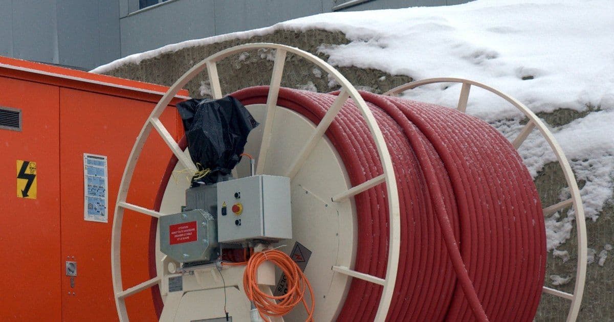
Mine power feeder cables carry medium-voltage (MV) power from the mine substation to switchhouses, portable substations and power centres. They are fixed or semi-stationary links, unlike the trailing and reeling cables that move with machines. Our guides to shovel and dragline cables, shearer and continuous miner cables and LHD and jumbo cables cover those machine cables.
The National Institute for Occupational Safety and Health (NIOSH) funded a 2006 study of these systems. It said modern underground coal mines generally have 15 or more miles (about 24 km) of high-voltage (HV) power cable, at 12.47 to 14.4 kV.
Key Takeaways
- Underground HV cables on resistance-grounded systems in US coal mines need a metallic shield on each power conductor, grounding conductors and an insulated ground-check conductor (Code of Federal Regulations, 30 CFR 75.804).
- No section of Part 75 Subpart I requires Mine Safety and Health Administration (MSHA) flame-resistance acceptance for HV feeder cables, unlike trailing cables (75.600-1) and HV longwall cables (75.822).
- Energised HV cables other than trailing cables must not be moved or handled (75.812). If MSHA permits an energised power centre or transformer move, only a qualified person in approved, tested insulated gloves may move its cables.
- Queensland's Coal Mining Safety and Health Regulation 2017 caps earth fault current on underground HV circuits at 10 A, or 5 A on circuits supplying an explosion risk zone 1 (ERZ1), subject to the exclusions in s 191(2) (s 191).
- Modelled ground faults in the 2006 study carried nearly three times the neutral grounding resistor (NGR) current.
Where Feeder Cables Sit in a Mine Power System
Feeder cables sit between the mine substation and the switchhouses, portable substations and power centres that supply the machines. US underground coal rules put breakers for HV circuits entering the mine on the surface, "in no case installed either underground or within a drift" (75.800-1).
Lightning arresters go on each ungrounded, exposed power conductor leading underground, within 100 feet (about 30 m) of where the circuit enters the mine (75.521). Underground disconnects must sit within 500 feet (about 152 m) of shaft and borehole bottoms where main power circuits enter, and of other entry points (75.519). HV circuits also need a visibly open disconnect within 100 feet of their surface entry point, unless MSHA permits a more accessible site farther away (75.802(c)).
Section 75.1002 limits what may run in or inby the last open crosscut, or within 150 feet (about 46 m) of pillar workings or longwall faces. Only these qualify: shielded HV cables supplying permissible longwall equipment or continuous mining machines, interconnecting cables of permissible longwall equipment, intrinsically safe circuits, and cables supplying low- and medium-voltage permissible equipment.
In underground metal and nonmetal mines, shaft and borehole power cables must be fastened securely (57.12083). In Ontario, cables carrying power from surface to underground must be fed through a surface circuit breaker (Regulation 854, s 175(1)).
Guidance from the UK Health and Safety Executive (HSE), HSG278, says underground supply should not normally exceed 11,000 V. For equipment that is normally stationary but moved with power applied, the figure is 6,600 V.
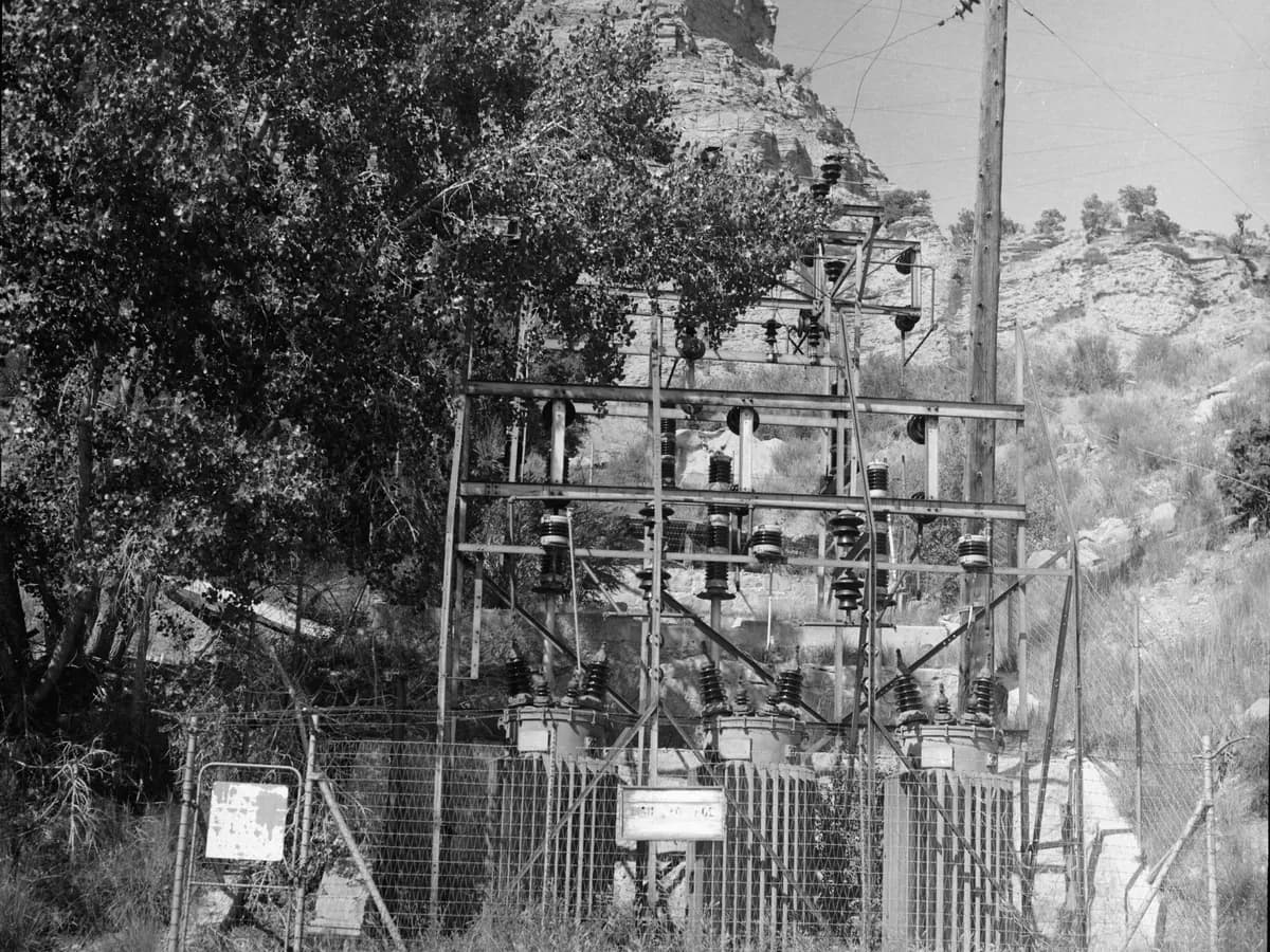
An outdoor substation serving a coal mine in Carbon County, Utah, photographed in 1983. Photo: David B. Merrill, Historic American Engineering Record (Library of Congress), public domain, via Wikimedia Commons, cropped.
How a Mine Feeder Cable Is Built
A mine feeder cable typically has three insulated power conductors, each with its own shield, plus grounding conductors and an insulated ground-check conductor, all under a jacket. Mine power feeder cables are often designated MP-GC, as in the 2006 study. Our shielded cable article explains these per-core earth screens.
The Insulated Cable Engineers Association and National Electrical Manufacturers Association (ICEA/NEMA) standard S-75-381 is titled "Portable and Power Feeder Cables for Use in Mines and Similar Applications". CSA Group, the Canadian standards body, publishes CSA C22.2 No. 96.1 for unarmoured mine power feeder cables in stationary or semi-stationary power distribution. It covers 5 to 35 kV at 100% and 133% insulation levels.
AS/NZS 1972:2006, reconfirmed in 2020, specifies cables for underground coal mines, feeder cables among them. South Africa's SANS 1520-2:2020, reaffirmed on 23 July 2026, covers HV flexible trailing cables for mines. BS 6708:1998, for flexible cables at mines and quarries, was withdrawn on 22 May 2026. IEC 60502-2, edition 3.1 of 2024, excludes cables for special installation and service conditions, naming "the mining industry" among them.
Insulation level matters because of earth faults. A New South Wales (NSW) code of practice notes that "phase voltage will rise to line voltage" during an earth fault on an earth fault current limited system. Queensland's coal regulation requires each part of an impedance-earthed or insulated-neutral system to have "a phase-to-earth insulation level equivalent to the phase-to-phase insulation level" (s 191(3)(b)).
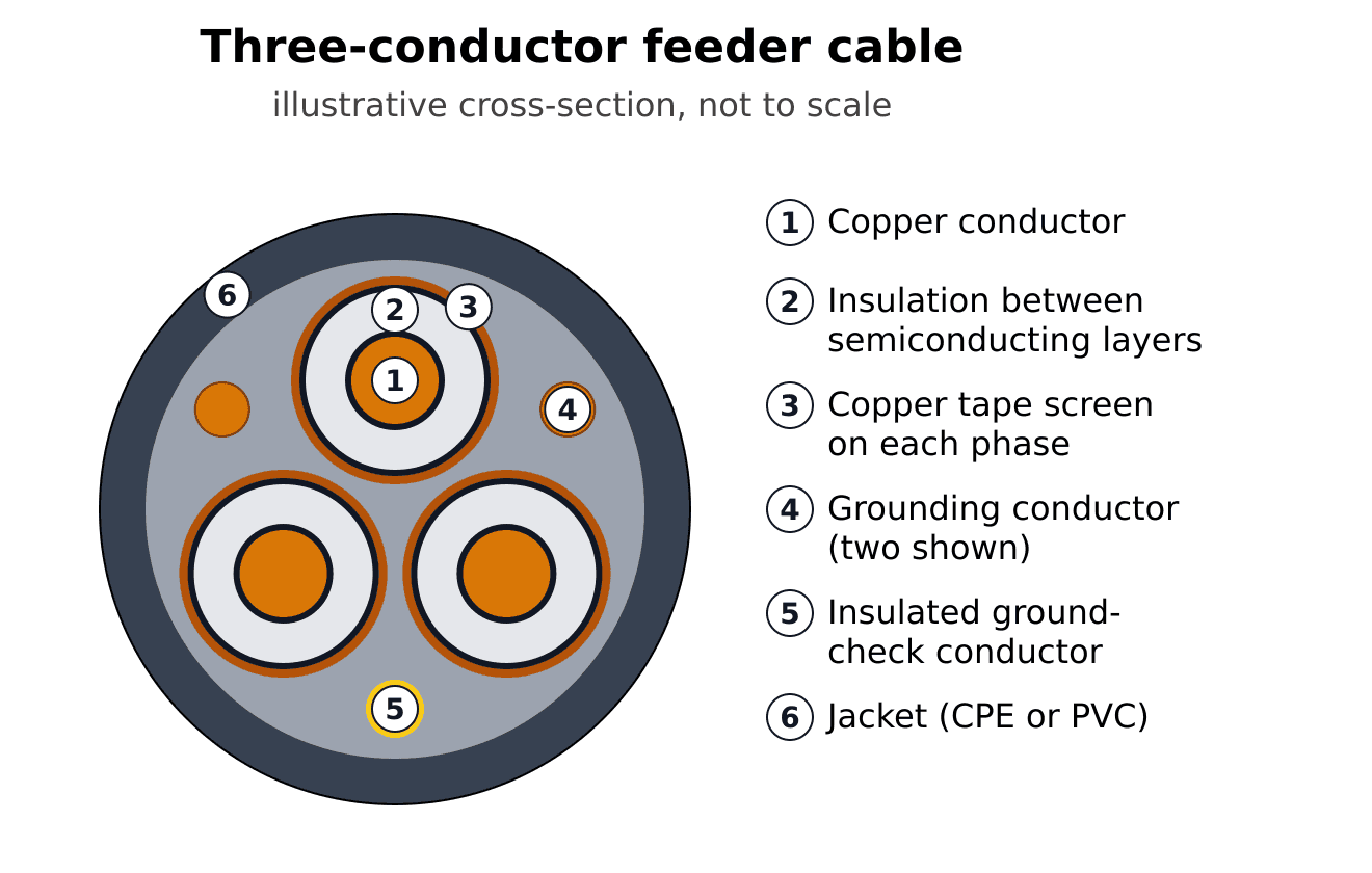
Illustrative cross-section of a three-conductor mine power feeder cable. Each phase conductor has insulation between semiconducting layers and its own copper tape screen; grounding conductors and an insulated ground-check conductor sit in the spaces between the cores. Under 30 CFR 75.804, underground HV cables on resistance-grounded systems need shields around each power conductor, ground conductors and an insulated ground-check conductor. Not to scale; materials and dimensions vary by design.
Cross-section key (readable on mobile):
- 1. Copper phase conductor.
- 2. Insulation between semiconducting layers.
- 3. Copper tape screen on each phase.
- 4. Grounding conductors (two shown).
- 5. Insulated ground-check conductor.
- 6. Outer jacket (CPE or PVC).
US Rules for Underground and Surface Feeders
Under Part 75 Subpart I, US underground coal HV feeders must be resistance grounded, ground-check monitored and shielded, unless an exception applies. Parts 75 and 77 call anything above 1,000 V "high voltage" (75.2, 77.2), while Part 57, for underground metal and nonmetal mines, calls anything above 650 V "high potential" (57.2).
HV circuits extending underground need a neutral grounded through a resistor at the source transformers, plus a grounding circuit run with the power conductors (75.802). The resistor must keep the voltage drop in the external grounding circuit to 100 V or less during a fault (75.801). A fail-safe ground-check circuit of no more than 96 V, or an approved equivalent, must open the breaker if the ground or pilot wire breaks (75.803, 75.803-1).
Under 75.802(b), MSHA may permit ungrounded HV circuits to stationary equipment only if it finds no hazard. Such circuits must be steel armoured or in grounded rigid steel conduit, or nominally 2,400 V or less with shielded conductors and one or more grounding conductors whose combined cross-sectional area is at least half that of one power conductor.
Underground HV cables on these systems need a metallic shield around each power conductor, one or more grounding conductors whose combined cross-sectional area is at least half that of one power conductor and an insulated ground-check conductor (75.804). Couplers on circuits above 660 V must be three-phase with a full metallic shell, unless MSHA permits no less effective non-metal couplers (75.805).
Power wires must sit on well-insulated insulators clear of combustible material, roof and ribs (75.516). Its exemptions include "specially designed cables conducting high-voltage power to underground rectifying equipment or transformers".
Under 75.812, energised HV cables other than trailing cables must not be moved or handled at any time. When MSHA permits an energised power centre or portable transformer move, only a qualified person in approved and tested insulated wireman's gloves may move its attached cables.
Surface Mines and Flame Resistance
Part 77 covers surface coal mines and the surface work areas of underground coal mines. It requires HV transmission cables to be protected from damage (77.807). Resistance-grounded systems need a fail-safe ground check of 96 V or less (77.803, 77.803-1).
No section of Part 75 Subpart I requires MSHA flame-resistance acceptance for HV feeder or distribution cables. Trailing cables (75.600-1) and HV longwall cables (75.822) must be accepted or approved as flame resistant. During excavation, conductors below the collar of a slope or shaft need flame-resistant insulation (77.1914(b)).
What MSHA Inspectors Check
MSHA's August 2026 Electrical Inspection Procedures Handbook has inspectors confirm that HV power cables going underground are shielded, which an SHD marking indicates. These checks start above 650 V at metal and nonmetal mines and above 1,000 V at coal mines. They also check that:
- HV cables routed underground run in regularly travelled airways (75.807 requires regularly inspected air courses and haulageways);
- guarding is provided where HV cables hang below 6½ feet (about 2 m) in places miners work or travel;
- HV couplers are latched, secured and free of damage;
- any cable in direct sunlight has an outer jacket resistant to ultraviolet light.
Inspectors test a representative number of splices in shielded cables with a non-contact voltage detector; a voltage indication suggests missing or discontinuous shielding. Where a doughnut-type current transformer detects ground faults, equipment grounding conductors, conductor shields included, "must not be installed through the current transformer". At surface transformer stations, the handbook says "Shielded cable may be considered as guarding."
Capacitance, Ground Faults and Relay Selectivity
Shielded feeder cable adds capacitance that can push ground-fault current well above the NGR current and upset relay selectivity. The 2006 NIOSH-funded study puts the capacitance of shielded mine cables "on the order of 110 pF/ft". Its measured value for 500 feet of 15 kV 4/0 mine power feeder averaged about 0.050 µF per phase, within 10% of the calculated value.
The study calls a 25 A NGR with a 10 A pickup, 40% of the limit, common practice for complying with 75.801. In its model of one representative 12.47 kV system, simulated fault current exceeded the NGR current "by a factor of nearly three in all cases". The system was "prone to loss of selectivity", and a simulated resonant fault produced "approximately three times the rated voltage". The chart plots the six modelled faults from the study's Table VII.
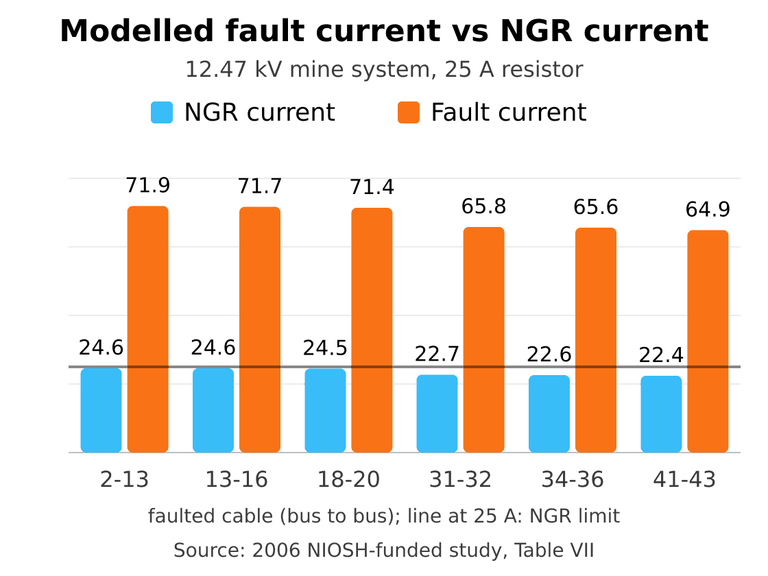
Modelled single line-to-ground faults on six cables of a representative 12.47 kV underground coal mine distribution system with a 25 A neutral grounding resistor: current through the resistor (22.4 to 24.6 A) against total fault current (64.9 to 71.9 A). Source: Table VII of Detrimental effects of capacitance on high-resistance-grounded mine distribution systems, a NIOSH-funded study published in 2006. Retrieved October 2026.
Chart data (readable on mobile):
- Cable 2–13: NGR current 24.6 A; fault current 71.9 A.
- Cable 13–16: NGR current 24.6 A; fault current 71.7 A.
- Cable 18–20: NGR current 24.5 A; fault current 71.4 A.
- Cable 31–32: NGR current 22.7 A; fault current 65.8 A.
- Cable 34–36: NGR current 22.6 A; fault current 65.6 A.
- Cable 41–43: NGR current 22.4 A; fault current 64.9 A.
Rules and guidance elsewhere address earth fault current and tripping ratios.
- Source: UK HSG278 (HSE guidance) — Earth fault current: No system above 1,200 V with over 150 A prospective earth fault current below ground — Earth leakage tripping: Ratio at least 3:1, preferably 5:1
- Source: NSW code — Earth fault current: As low as reasonably practicable — Earth leakage tripping: Ratio at least 10 to 1 against the limitation current
- Source: Queensland s 191 and s 192 — Earth fault current: 10 A on HV circuits, 5 A on ERZ1 circuits — Earth leakage tripping: 1 A or less on HV circuits outside an ERZ1
The Queensland limits above are subject to the exclusions in sections 191(2) and 192(5): intrinsically safe circuits; circuits operating at not more than 55 V to earth and fully contained in a non-explosion risk zone (NERZ) or an explosion-protected enclosure; and circuits isolated from earth. Section 192(1) applies to circuits operating above 55 V to earth. These exclusions do not remove the separate earth-continuity and lockout protection requirements for reeling, trailing and feeder cable circuits in section 192(4).
Couplers, Splices and Testing
US rules fix the uncoupling order and splice continuity, and IEEE guides cover field testing. Under 75.805, the ground-check conductor breaks first and the ground conductors last when uncoupling. Splices "shall provide continuity of all components" (75.804(b)).
A 1982 coupler study of 15 kV-class couplers concluded that "partial discharge appears to be the failure mechanism of concern". It added that "the quality of installation of a coupler onto cable is quite critical."
IEEE 400-2023 guides field testing of shielded power cable insulation at 5 kV and above, and IEEE 400.3-2022 covers partial discharge field diagnostics. IEC 60270:2025 sets partial discharge measurement techniques, while IEC 60885-3:2015 covers measurements on cable lengths but not on installed systems. CSA M421:23 clause 7.6.2 now has a note to use IEEE 400 test methods.
In Queensland, underground mines' safety and health management systems must provide for repairing and testing feeder cables (s 189). AS/NZS 1747:2022 covers that work for reeling, trailing and feeder cables across mining, tunnelling, quarries and dredges.
What MSHA Fatality Reports Show
MSHA fatality reports show deaths on HV mine circuits that were not de-energised and locked out. In some, ground-check protection had also failed.
- 1997, Kentucky, underground coal, 7,200 V: the splice box circuit "had not been deenergized, grounded, locked out, or suitably tagged", and a shorted ground monitor stopped the switch tripping.
- 2002, Virginia, underground coal, 12,470 V: MSHA cited the "failure to lock out the disconnecting device", tag it and ground the circuit, and the surface breaker "was inoperative".
- 2004, Virginia, underground coal, 7,200 V: a worker contacted an energised HV feed-through receptacle while cleaning it, and a bent pilot pin had short-circuited the fail-safe ground-check circuit.
- 2025, Montana, underground platinum-group metals, 13,200 V: MSHA said the operator did not (1) de-energise or lock out equipment, (2) label principal power switches, or (3) give safe-work instruction.
Rules Outside the US
Outside the US, feeder rules stress earth fault limits, screening and armour.
Australia and Canada
In Queensland, each underground circuit supplying a reeling, trailing or feeder cable needs earth continuity protection and a lockout earth fault current protection device (s 192(4)(a)). The NSW code lists individually screened flexible feeder cables, with phase barriers in accessories, as a cable selection criterion. Its note says this "has proven to be a reliable risk control at underground coal mines". It also calls for earth screens on power conductors where reasonably practicable.
In Canada, CSA M421:23 applies to movable equipment fed by mine power feeders where ground fault potential rise must stay within tolerable touch voltages. It adds armoured cable rules (clause 4.3.4) and extends its cable protection clause, 4.3.1.7, from portable power cables to all cables.
Ontario Regulation 854 s 164 requires a current-limited, ground-fault-protected supply with a fail-safe ground-continuity circuit for electrical mobile equipment above 300 V to ground. Section 175 adds the surface breaker for underground feeds.
Chile, Peru, South Africa and the UK
Chile's DS 132 requires feeders above 600 V to be armoured, with earthed armour, or for flexible feeders an earthed concentric screen on each phase (Art 222). Unarmoured cables may be used with fire-safe specifications, full insulation and the authorisation of Sernageomin, Chile's mining regulator. Runs go on the gallery walls opposite water and air lines, or higher (Art 220), and cross traffic areas at least 2.10 m up or buried (Art 225).
Peru's DS 024-2016-EM requires cables in a mine shaft or escape route to be flame non-propagating and low smoke (Art 362 d)). Under Art 360, installations follow the Código Nacional de Electricidad.
South Africa's 2015 regulations require the employer to take reasonably practicable measures to ensure suspended cables that could cause a fire in stopes, haulages or shafts are protected (3.7). That protection covers discriminating and correctly rated switchgear, plus fire-retardant cables or coatings. The employer's measures must also ensure earthing conductors withstand the maximum possible earth fault current (3.20), and that buried cables, or those open to mechanical damage, are armoured (3.22).
In the UK, HSE guidance says metallic screens on fixed cables above 650 V "should be of steel wire armour or other suitable hard metallic sheath". Our SANS 1520 guide and BS 6708 guide explain those standards' cable types.
Our Feeder and MV Cable Designs
Our related designs use US, British, South African and German design references. Their pages are design references, not approval certificates, and the approval each jurisdiction requires is confirmed per order.
- Type MP-GC: our datasheets list a three-conductor feeder from 2 to 15 kV, insulated with ethylene propylene rubber (EPR) at 2 kV or cross-linked polyethylene (XLPE) above. Each phase is shielded and copper-tape screened, with two bare grounding conductors, a yellow ground-check conductor and a chlorinated polyethylene (CPE) or polyvinyl chloride (PVC) jacket. Their design reference is ICEA S-75-381 / NEMA WC 58.
- BS 6708 Type 630/631: our datasheet lists a 3.8/6.6 kV supply cable with EPR insulation, braided tinned copper and nylon phase screens, and galvanised steel pliable armour under a chloroprene sheath.
- SANS Type 611: our datasheets describe Types 611, 622 and 633 as MV cables for reeling and section-feeder duty, with individually screened cores, at 6.35/11, 12.7/22 and 19/33 kV.
- NTMCGCWÖU: our datasheet lists a single-core MV cable rated 3.6/6 to 18/30 kV, flexible and concentrically screened, that connects switchgear, mobile transformers and substations to overhead lines. It has EPR insulation, a tinned-copper screen and a red rubber jacket.
How to Specify a Mine Feeder Cable
Specify the electrical system first, then the rules, construction, route and accessories. Related designs sit in our mining and tunnelling range.
- Voltage. Give the system voltage, voltage class and insulation level.
- Rules. Name the jurisdiction and the cable standard it calls for.
- Construction. Define shields and grounding conductors. Under 75.804, an external ground-check conductor must be at least No. 8 American Wire Gauge (AWG), about 8.4 mm², and an internal one No. 10 AWG (about 5.3 mm²).
- Route. Map airways, boreholes, shafts, guarding, and burial or armour needs.
- Jacket. Match it to sunlight, flame-resistance or shaft requirements.
- Couplers and splices. Choose couplers that break the ground check first, and splices that keep every component continuous.
- Grounding. Check NGR sizing, relay settings and capacitance in a system study.
- Tests and documents. Agree factory and field tests, such as IEEE 400 methods, and approval documents.
Frequently Asked Questions
Does a mine feeder cable need MSHA flame-resistance approval?
In US underground coal mines, no section of Part 75 Subpart I requires MSHA flame-resistance acceptance for high-voltage feeder cables. Shaft work differs: 77.1914(b) requires flame-resistant insulation below the collar during excavation. Peru requires flame non-propagating, low-smoke cables in shafts (Art 362 d)).
What is an MP-GC cable?
MP-GC is a designation often used for mine power feeder cables, as in a NIOSH-funded 2006 study. Such a cable typically has three shielded power conductors, grounding conductors and an insulated ground-check conductor. ICEA S-75-381 covers portable and power feeder cables for mines.
How does a feeder cable differ from a trailing cable?
A mine feeder cable is a fixed or semi-stationary link, while a trailing cable moves with its machine. In US underground coal mines, trailing cables must be MSHA accepted or approved as flame resistant (75.600-1), which no Subpart I section requires of HV feeders.
Why are mine feeder cables shielded?
Mine feeder cables are shielded because US underground coal rules require per-phase shields and the NSW code rates screening a proven risk control. In US underground coal mines, 75.804 requires a metallic shield around each power conductor on resistance-grounded systems. The NSW code calls individually screened flexible feeder cables "a reliable risk control at underground coal mines".
Should a mine feeder use 100% or 133% insulation?
Whether a mine feeder uses 100% or 133% insulation depends on the earthing system and the governing rules. CSA C22.2 No. 96.1 covers both 100% and 133% insulation levels. Queensland requires each part of an impedance-earthed or insulated-neutral system to have phase-to-earth insulation equal to its phase-to-phase level (s 191(3)(b)).
How should borehole and shaft cables be supported?
Borehole and shaft cables should be fastened securely so the sheath, insulation and conductors take no undue strain, as 57.12083 requires in US underground metal and nonmetal mines. HSE guidance says installed cables should be properly supported at suitable intervals along their length.
Enquire About Mine Feeder Cable
Send our engineering team, through the contact page, your system voltage and grounding method, route length and installation (airway, borehole, shaft or buried), and conductor size. Include the number of grounding and ground-check conductors, jacket needs, coupler type and the standard your jurisdiction requires.
About the Author
Jyen is a technical and operations engineer at TEBAOFLEX, responsible for the company's online platforms. This guide draws on US federal mine safety regulations, MSHA inspection guidance and fatality reports, NIOSH-funded and university research, mining regulations and guidance from Australia, Canada, Chile, Peru, South Africa and the UK, standards catalogue records, and TEBAOFLEX product datasheets. The product pages cited are TEBAOFLEX's own; requirements quoted from regulators and standards bodies describe their scope, not certification or approval of our products.
Cover photo: "Sous-station MT-BT" by Flo2110, CC BY-SA 3.0, via Wikimedia Commons, cropped.
