What the video shows
A 70-second walkthrough of the 14/25 kV shovel reeling cable, combining schematic tail-reel and construction animations with sample close-ups and laboratory flame-test footage.
The video illustrates a sample, process, or operating context. Final product construction, suitability, standards, and test acceptance criteria are confirmed against the ordered specification.
By TEBAOFLEX Jyen. Updated on October 23, 2026.
Media delivery note: the web video is 1080p/60fps; the eight frame images are 1280×720. Use the full-size image links to inspect details.
TL;DR: This 70-second (1:10) video presents our 14/25 kV (Uₘ 30 kV) TEBAOFLEX F-(N)TSCGEWOEU 3x120+3x70/3 mm² electric mining shovel reeling cable built to DIN VDE 0250-813 (2026). It pairs schematic 3D 295-BII rope shovel tail-reel and 6-layer cutaway animations (0:03 to 0:53) with 100% real production sample photos and live laboratory flame test video (0:00 to 0:03and0:53 to 1:03). Three120 mm²Class 5 copper phase cores (IEC 60228, 2026), triple-extruded90 °CHEPR (36 kV AC test), and three70/3 mm²split earth cores sit inside a black5GM3EPR inner bedding. A vulcanized anti-torsion braid (±100 °/m, 5,400 N pull) and a red5GM5PCP outer jacket (67.9 mm nominal OD) pass live IEC 60332-1-2 flame testing.
On open-pit crawler electric mining rope shovels (295-BII class), walking draglines, and bucket-wheel excavators, medium-voltage trailing and reeling cables must deliver 14/25 kV (Uₘ 30 kV) power across blasted rock benches. At the same time, they must survive 5,400 N dynamic pull and multi-plane bending over tail fairlead rollers. This video page examines our 14/25 kV F-(N)TSCGEWOEU 3x120+3x70/3 mm² cable in a 70-second walkthrough. It covers the 6-layer strip-back, our real 2026.3.14 factory specimen, and live vertical flame chamber footage. Below, you can watch the full video, check the scene log, review DIN VDE 0298-4 ampacity tables, and use our shovel reel checklist. This page was reviewed by the TEBAOFLEX editorial engineering board.
What Happens in Each Scene of the 70-Second Product Video?
The 70-second video combines two visual formats so mining electrical engineers can verify both shovel tail-reel motion and real factory quality. First, it shows 100% real factory specimen photos and live IEC/EN 60332-1-2 laboratory flame test video (0:00 to 0:03 and 0:53 to 1:03). Second, it shows schematic 3D 295-BII open-pit shovel and 6-layer CAD cutaway animations (0:03 to 0:53 and 1:03 to 1:10). The table below logs every scene by timestamp.
Timestamp
0:00 - 0:03
- Video Scene & Visual Mode: Opening Cover Card (Real sample + 295-BII).
- Key Technical Details Shown on Screen: Shows a real red sample embossed
F-(N)TSCGEWOEUand printedTEBAOFLEX F-(N)TSCGEWOEU 14/25kV 3x120+3x70/3 VDE 0250-813 2026.
0:03 - 0:08
- Video Scene & Visual Mode: 01 / Cross-Section Reveal (Schematic 2D/3D).
- Key Technical Details Shown on Screen: Reveals the
14/25 kV (Um 30 kV) 3x120 + 3x70/3layout with90 °CHEPR, split earth cores,5GM3inner sheath, braid, and red5GM5jacket.
0:08 - 0:11
- Video Scene & Visual Mode: 02 / Shovel Scene: Step 01 (Schematic 3D).
- Key Technical Details Shown on Screen: Shows
295-BII Open-Pit Electric Mining Rope Shovel(TRI STAR MINING 295 B) fed at14/25 kV (371 A)on a rock bench.
0:11 - 0:14
- Video Scene & Visual Mode: 02 / Bench to Tail Reel: Step 02 (Schematic 3D).
- Key Technical Details Shown on Screen: Labels
1. 14/25 kV Mine Bench Substation Skid,2. Bench Guide Rollers & Tail Fairlead, and3. 295-BII Shovel Tail Motorized Cable Reel.
0:14 - 0:18
- Video Scene & Visual Mode: 02 / Torque Pay-Out: Step 03 (Schematic 3D).
- Key Technical Details Shown on Screen: Highlights
Automatic Torque-Controlled Pay-Out & Take-UpwithMin. Bending Radius R >= 10xD (680 mm)during+14.4 mshovel travel.
0:18 - 0:21
- Video Scene & Visual Mode: 02 / Fairlead & X-Ray: Step 04 (Schematic 3D).
- Key Technical Details Shown on Screen: Zooms into
Tail Fairlead & Red 5GM5 CR/PCP Outer Jacket(5,400 Npull) and a3D X-Ray Cutawayof the3x120 + 3x70/3cores.
0:21 - 0:39
- Video Scene & Visual Mode: 03 / 6-Layer Strip-Back (06 to 01) (3D CAD cutaway).
- Key Technical Details Shown on Screen: Strips back
06 Red 5GM5 Sheath,05 Anti-Torsion Braid,04 Black 5GM3 Bedding,03 3x70/3 Earth,02 90C HEPR, and01 Class 5 Cu.
0:39 - 0:48
- Video Scene & Visual Mode: 04 / 3D & 2D Construction Summary (Schematic 3D/2D).
- Key Technical Details Shown on Screen: Combines all 6 layer callouts (
01 to 06), a3x120 + 3x70/3 SECTIONinset (65.9 to 69.9 mm), and a 6-row table.
0:48 - 0:53
- Video Scene & Visual Mode: 05 / Key Technical Specifications (Engineering card).
- Key Technical Details Shown on Screen: Lists
14/25 kV (36 kV test),3x120+3x70/3(371 A),60332-1-2 Pass,5,400 N Pull(±100 °/m),+90C / 250C SC, and67.9 mm Nom..
0:53 - 0:56
- Video Scene & Visual Mode: 06 / Real Sample & QC Tag (01 of 03) (Real photo).
- Key Technical Details Shown on Screen: Shows the uncropped stripped sample, handwritten QC tag (
Date: 2026.3.14), embossed14/25KV F-(N)TSCGEWOEU, and oblique cuts.
0:56 - 0:59
- Video Scene & Visual Mode: 06 / Real 6-Core End-Face (02 of 03) (Real photo).
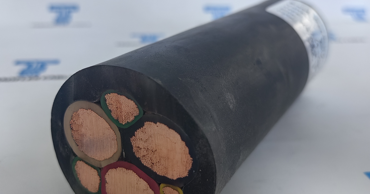
- Key Technical Details Shown on Screen: Shows the real
3x120+3x70/3 mm²6-core end-face cut and gloved handheld inspection (67.9 mmnominal OD).
0:59 - 1:03
- Video Scene & Visual Mode: 06 / Live Flame Test (03 of 03) (Live lab video).
- Key Technical Details Shown on Screen: Shows
LIVE LAB VIDEO 01and02vertical flame tests (IEC/EN 60332-1-2) and the self-extinguishedPOST-BURN SPECIMEN.
1:03 - 1:10
- Video Scene & Visual Mode: Closing Brand Card (Graphic summary card).
- Key Technical Details Shown on Screen: Displays
TEBAOFLEX F-(N)TSCGEWOEU 14/25 kV 3x120+3x70/3 mm² Heavy-Duty Electric Mining Shovel & Excavator Cable(Publisher: TeBaoFlex Jyen).
Video Scope Note: The14/25 kVbench substation skid, guide rollers,295-BIIrope shovel tail reel, 3D X-ray view, and 6-layer strip-back animations (0:03 to 0:53) are schematic engineering views. They are not mine site footage and are not to scale. Real physical factory sample photos (Date: 2026.3.14) and live laboratoryIEC/EN 60332-1-2vertical flame test clips appear at0:00 to 0:03and0:53 to 1:03. All electrical, thermal, and mechanical values represent official ratings under DIN VDE 0250-813, IEC 60228, and DIN VDE 0298-4.
Video at a Glance: Video & Sample Technical Summary
The table below lists the verified specifications shown in the video and defined by DIN VDE 0250-813 (2026).
Parameter
Commercial Model Designation.
- Verified Video & Standard Specification:
TEBAOFLEX F-(N)TSCGEWOEU 14/25 kV 3x120 + 3x70/3 mm².
Reference Standards.
- Verified Video & Standard Specification: DIN VDE 0250-813, DIN EN 60228 / IEC 60228 Class 5, IEC/EN 60332-1-2.
Rated & Test Voltage.
- Verified Video & Standard Specification:
U0/U = 14/25 kV AC(maxUm = 30 kV AC); routine 5-min AC test 36 kV AC.
Phase Conductors (Layer 01).
- Verified Video & Standard Specification: 3 x 120 mm² Class 5 copper phase cores (
14.3 mmdia., 371 A,<= 0.161 Ω/km, 17.16 kA 1s SC).
Split Protective Earth (Layer 03).
- Verified Video & Standard Specification: 3 x 70/3 mm² (
3 x 23.3 mm²=70 mm²total) Class 5 copper in 3 outer valleys (<= 0.272 Ω/kmat 20 °C).
MV Insulation & Field Control.
- Verified Video & Standard Specification: Triple-extruded inner semi-con screen + 90 °C HEPR (
3GI3) dielectric + strippable outer semi-con (<= 500 Ohm.m).
Inner Bedding & Anti-Torsion.
- Verified Video & Standard Specification: Pressure-extruded black
5GM3EPR inner sheath + vulcanized polyester braid (±100 °/m, 5,400 N at15 N/mm²).
Reeling Outer Sheath (Layer 06).
- Verified Video & Standard Specification: Heavy-duty red Polychloroprene (
5GM5 CR/PCP) per DIN VDE 0207-21, flame-retardant per IEC/EN 60332-1-2.
OD, Weight, Temp & Bending.
- Verified Video & Standard Specification: 67.9 mm nominal OD (
65.9 to 69.9 mm); 8,200 kg/km mass;-25 to +60 °Cflex (-40 °Cfixed); min bendR >= 10 x D(680 mm).
How Does the Video Illustrate 295-BII Open-Pit Rope Shovel Reeling?
An F-(N)TSCGEWOEU 14/25 kV cable is a heavy-duty medium-voltage flexible trailing and reeling cable built to DIN VDE 0250-813 for open-pit electric rope shovels and excavators. It houses three 90 °C HEPR phase cores and three split earth cores inside a torsion-reinforced 5GM3 / 5GM5 double rubber sheath.
In Section 02 (0:08 to 0:21), a four-step 3D view shows how our 3x120+3x70/3 mm² cable feeds a 295-BII crawler electric mining rope shovel.
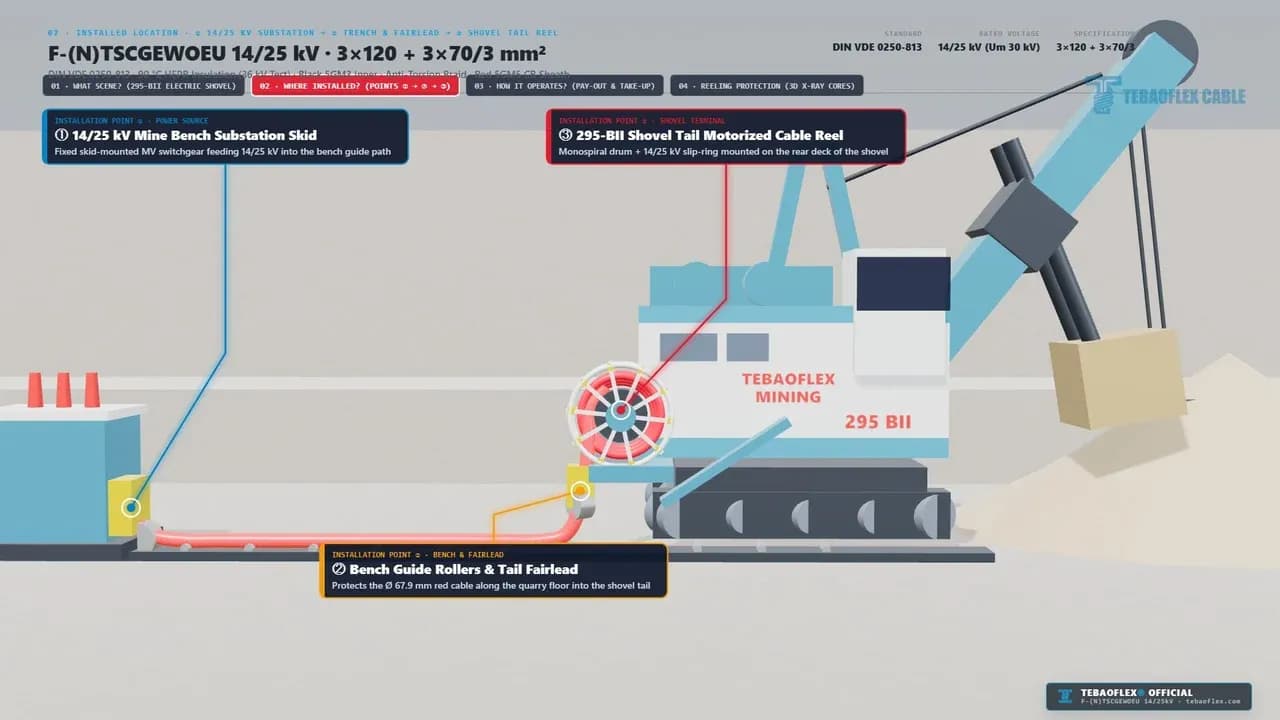
- 295-BII Open-Pit Electric Mining Rope Shovel (
0:08 to 0:11). First, the clip shows a crawler rope shovel (TRI STAR MINING 295 B) loading a haul truck while drawing 14/25 kV (371 A) power (~16.06 MVAat25 kV). - Substation Skid to Shovel Tail Reel (
0:11 to 0:14). Second, as shown above, the cable runs from1. 14/25 kV Mine Bench Substation Skidacross2. Bench Guide Rollers & Tail Fairlead(67.9 mmOD). The moving end winds onto3. 295-BII Shovel Tail Motorized Cable Reel(14/25 kVslip-ring). - Torque-Controlled Pay-Out & Take-Up (
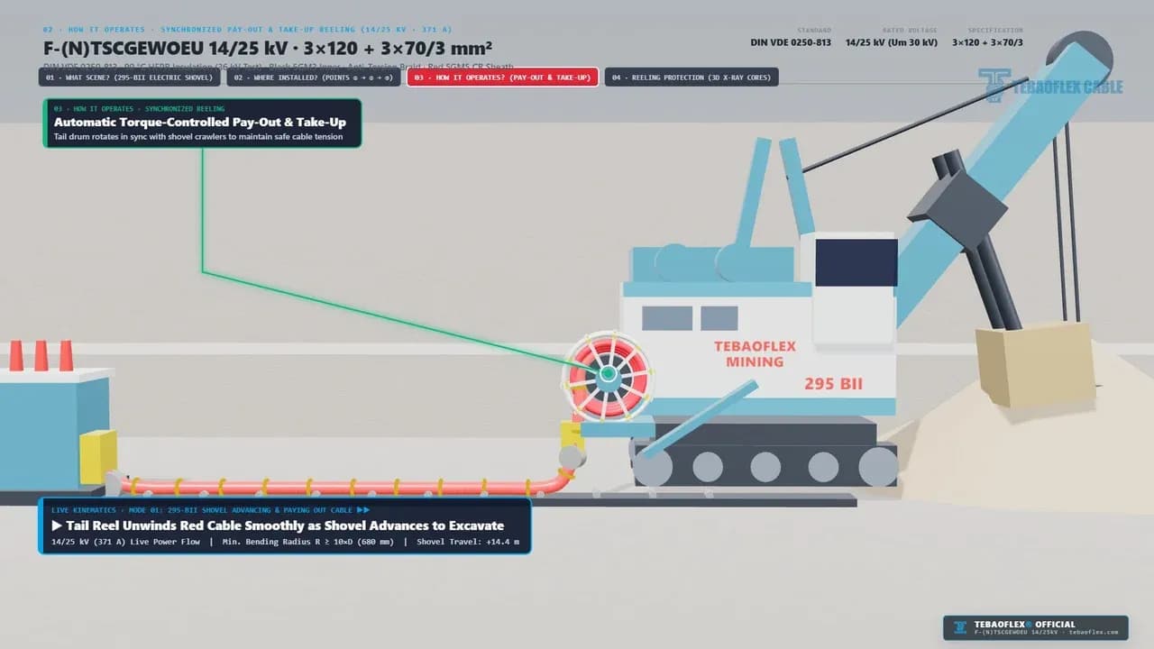
0:14 to 0:18). Third, as shown below, the motorized tail reel pays out and takes up cable during+14.4 mshovel travel. It keeps dynamic bending aboveR >= 10 x D(680 mm).
- Tail Fairlead & 3D X-Ray Core Geometry (
0:18 to 0:21). Finally, as shown below, the cable passes through the tail fairlead under 5,400 N (15 N/mm²) pull. A 3D X-ray cutaway highlights the3x120 mm²phase cores,3x70/3 mm²split earth cores, and±100 °/manti-torsion braid.
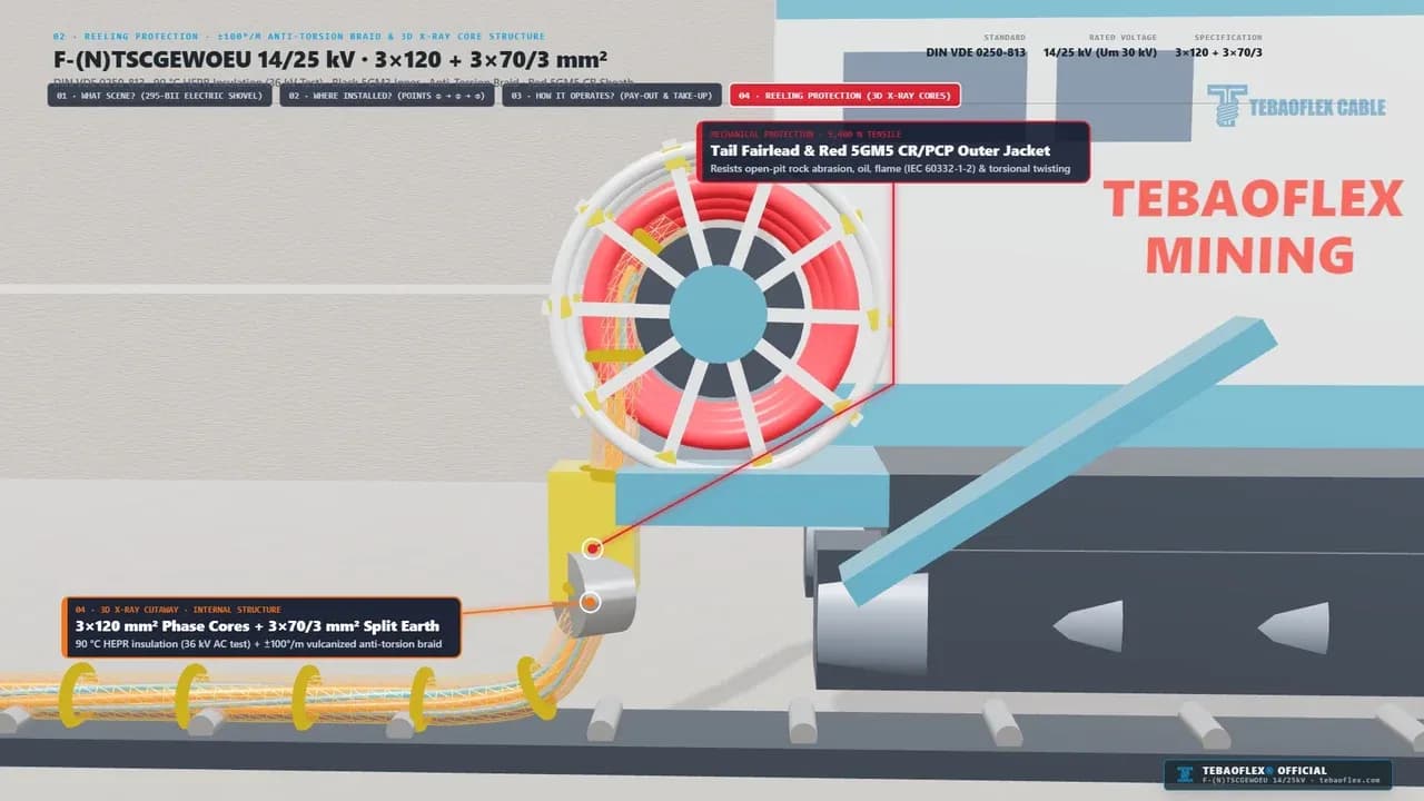
A shovel tail motorized cable reel is a torque-regulated monospiral or level-wind drum mounted at the rear counterweight of an electric mining shovel. It automatically pays out and winds up the 14/25 kV trailing cable as the crawler tracks advance or retreat.
For example, when a 295-BII rope shovel crawls +14.4 m along a blasted rock bench, the rear fairlead rollers impose both reverse bending (R >= 680 mm) and axial twisting. Without a vulcanized braid locked between inner and outer rubber sheaths, core birdcaging quickly ruins the 14/25 kV semi-con screens. To explore related mining and crane cables, see our reeling cable product hub, our mining and tunneling cable solutions, and our port and material handling crane guide.
How Does the 6-Layer DIN VDE 0250-813 Construction Handle 14/25 kV & 5,400 N?
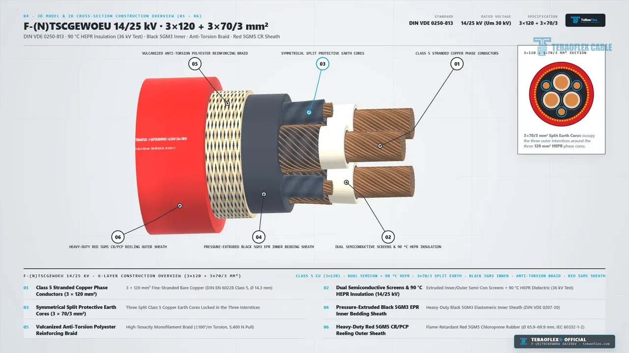
In Section 03 (0:21 to 0:39) and Section 04 (0:39 to 0:48), the video strips our F-(N)TSCGEWOEU 14/25 kV 3x120+3x70/3 mm² cable from its red outer jacket (Layer 06) down to its 120 mm² copper conductors (Layer 01).
DIN VDE 0250-813 is the German VDE standard governing medium-voltage (6/10 kV to 18/30 kV) elastomeric-insulated flexible trailing and reeling cables for open-pit mining excavators, rope shovels, and cranes (VDE Verlag, 2026).
You can browse related German medium-voltage rubber cable types in our VDE / DIN cable standards catalog.
Layer 06 & Layer 05: Heavy-Duty Red 5GM5 CR/PCP Outer Sheath & Anti-Torsion Braid (0:21 to 0:27)
The outer jacket (Layer 06) uses heavy-duty red Polychloroprene (5GM5 CR/PCP) per DIN VDE 0207-21 and DIN EN 50363-2-1. At 67.9 mm nominal outer diameter (65.9 to 69.9 mm), its high-visibility red compound contrasts sharply against grey bench rock. It also resists sharp rock abrasion, oil (IEC 60811-404), UV sunlight, and flame propagation (IEC 60332-1-2).
Beneath Layer 06 sits Layer 05, a vulcanized high-tenacity polyester anti-torsion reinforcing braid. It bonds the outer 5GM5 and inner 5GM3 sheaths together to stop core rotation under ±100 °/m torsion and 5,400 N (15 N/mm²) dynamic pull (DIN VDE 0250-813, 2026).
Layer 04 & Layer 03: Black 5GM3 EPR Inner Bedding & 3 x 70/3 mm² Split Earth Cores (0:27 to 0:33)
Under the anti-torsion braid, we extrude Layer 04, a pressure-vulcanized black 5GM3 EPR inner bedding sheath per DIN VDE 0207-20. It fills every interstitial valley and locks the six internal cores into a round, crush-resistant profile.
Symmetrical split protective earth geometry is a balanced 6-core medium-voltage layout where the 70 mm² protective earth is split into three 23.3 mm² (3 x 70/3 mm²) Class 5 copper cores. These three cores sit symmetrically in the outer valleys between the 120 mm² phase cores.
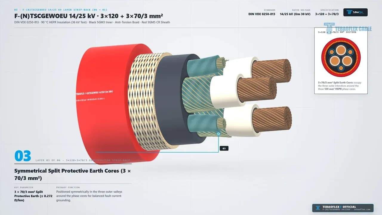
As shown at 0:31 above (Layer 03), each 23.3 mm² split earth core carries a semi-conductive contact covering. Together, the three parallel earth cores provide a low DC resistance of <= 0.272 Ω/km at 20 °C, equalizing zero-sequence impedance without enlarging the 67.9 mm outer diameter.
Layer 02 & Layer 01: Triple-Extruded 90 °C HEPR Insulation & 3 x 120 mm² Class 5 Copper (0:33 to 0:39)
Each phase core (Layer 02) is insulated with triple-extruded 90 °C HEPR (3GI3) (+90 °C operating, +250 °C short-circuit per DIN VDE 0207-20) between bonded inner and strippable outer semi-con screens (<= 500 Ohm.m). Every finished batch passes a 36 kV AC 5-minute routine dielectric test.
At the center (Layer 01) sits a 120 mm² Class 5 fine-stranded copper phase conductor (14.3 mm diameter) per DIN EN 60228 / IEC 60228 (2026). It delivers 371 A per phase (<= 0.161 Ω/km max DC resistance at 20 °C) and a 17.16 kA 1-second short-circuit rating (120 mm² x 143 A/mm² = 17.16 kA).
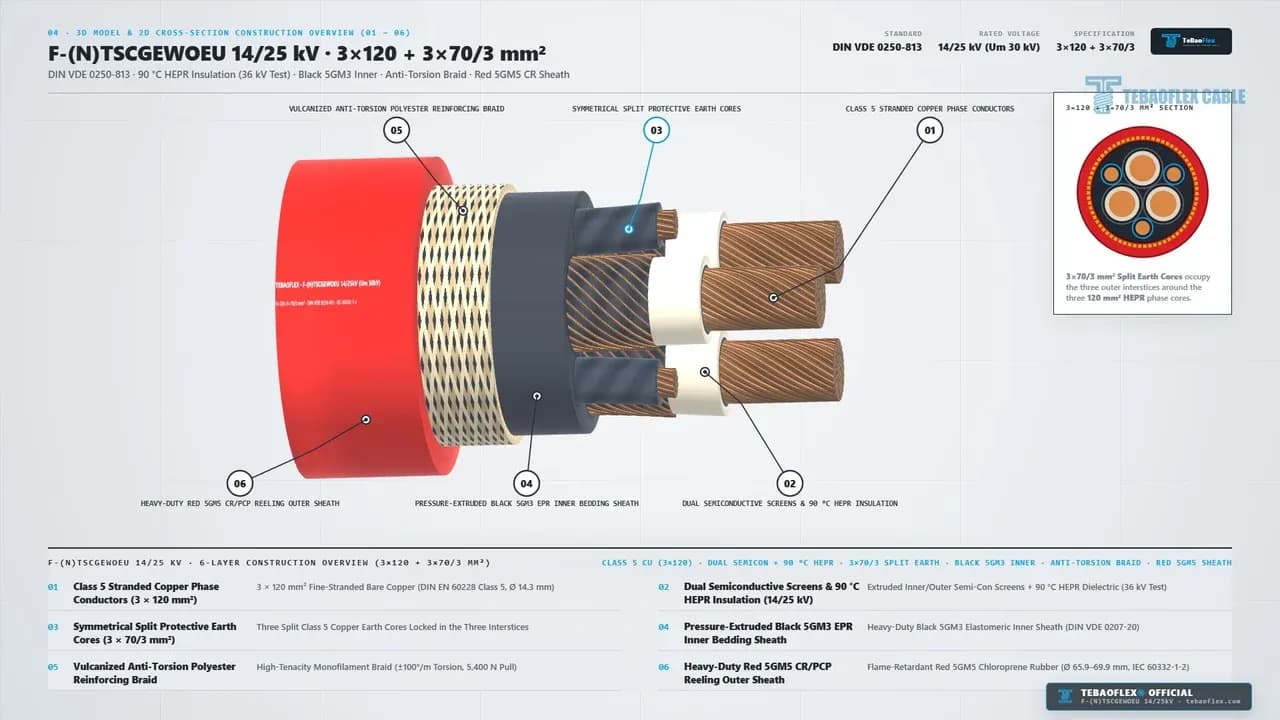
Layer No.
Layer 01.
- Structural Component: Phase Cores (
3 x 120 mm²). - Compound / Standard Code: Class 5 copper (
14.3 mmdia., IEC 60228). - Primary Mechanical & Electrical Function: Delivers 371 A (
<= 0.161 Ω/km, 17.16 kA SC) under continuous bending.
Layer 02.
- Structural Component: Triple-Extruded MV Insulation.
- Compound / Standard Code: Semi-con screens +
90C HEPR(DIN VDE 0207-20). - Primary Mechanical & Electrical Function: Controls
14/25 kV(30 kVmax) field stress and passes 36 kV AC 5-min test.
Layer 03.
- Structural Component: Split Earth (
3 x 70/3 mm²). - Compound / Standard Code: Three
23.3 mm²Class 5 PE cores + semi-con layer. - Primary Mechanical & Electrical Function: Provides balanced
70 mm²grounding (<= 0.272 Ω/km) in the 3 outer valleys.
Layer 04.
- Structural Component: Elastomeric Inner Bedding.
- Compound / Standard Code: Pressure-extruded black
5GM3EPR inner sheath. - Primary Mechanical & Electrical Function: Fills core gussets to lock core lay geometry and cushion rock crush impact.
Layer 05.
- Structural Component: Vulcanized Anti-Torsion Braid.
- Compound / Standard Code: Polyester textile braid (
±100 °/m,5,400 N). - Primary Mechanical & Electrical Function: Prevents corkscrewing and absorbs dynamic
295-BIIshovel tail-reel pull.
Layer 06.
- Structural Component: Red 5GM5 CR/PCP Outer Sheath.
- Compound / Standard Code: Polychloroprene
5GM5(DIN VDE 0207-21). - Primary Mechanical & Electrical Function: High-visibility rock abrasion, oil, UV, and
IEC 60332-1-2flame protection (67.9 mm OD).
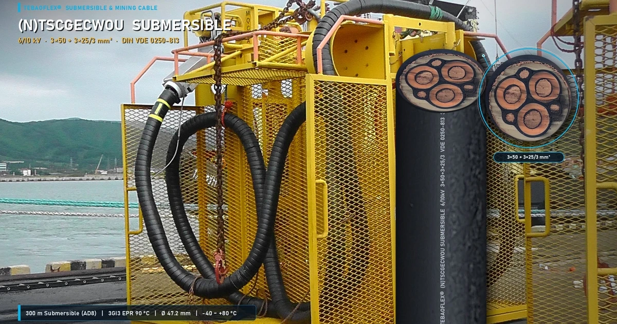
For other medium-voltage and crane applications, compare our (N)TSCGEWOEU+FO 6/10 kV 3x70+2x35/2+12FO fiber-optic reeling cable video, (N)TSCGECWOU Submersible 6/10 kV 3x50+3x25/3 mining pump cable video, and NSHTOU Crane-VS 4x16 mm² reeling cable video.
What Key Technical Specifications Are Confirmed at 0:48 to 0:53?
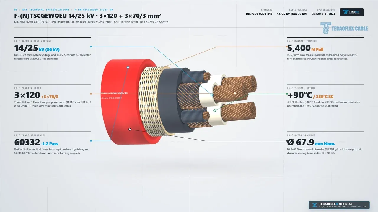
In Section 05 (0:48 to 0:53), the video summarizes the six governing ratings for F-(N)TSCGEWOEU 14/25 kV 3x120+3x70/3 mm².
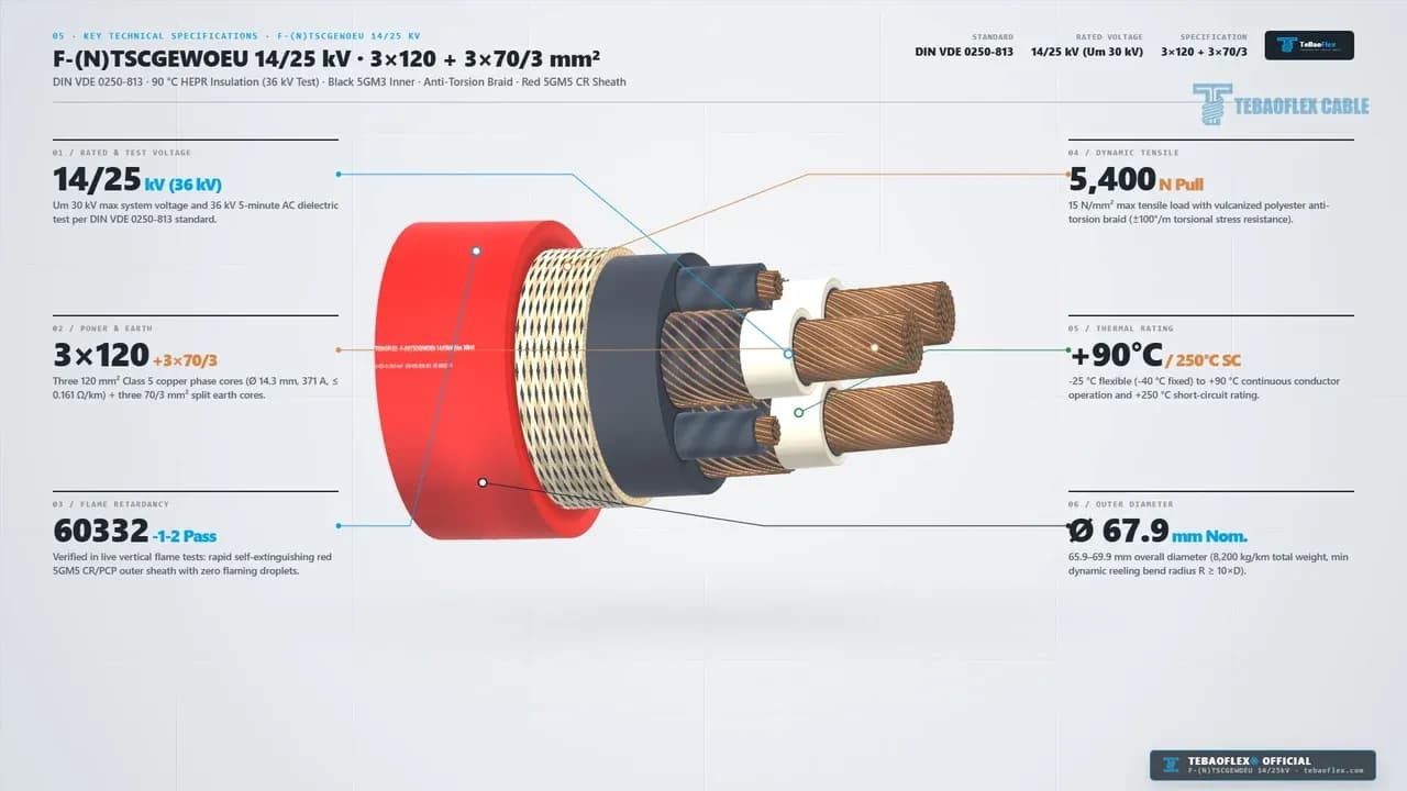
When specifying a trailing or reeling cable for a 295-BII open-pit rope shovel, engineers must balance apparent power delivery against tail-drum deadweight and pulling tension in Panel 04 and Panel 06 at 0:49 (DIN VDE 0250-813, 2026). For instance, operating at 14/25 kV (Uₘ 30 kV) instead of 6/10 kV allows three 120 mm² phase cores (371 A base ampacity) to supply 16.06 MVA at 25 kV while keeping net cable mass at 8,200 kg/km (8.20 kg/m). Across 3 x 120 mm² = 360 mm² of phase copper, the DIN VDE 0298-4 specific limit of 15 N/mm² provides a 5,400 N (~550 kgf) maximum dynamic pulling force. That equals the weight of 65.8 meters of suspended cable, giving plenty of tensile margin for horizontal bench pay-out (+14.4 m travel shown at 0:16).
Spec Panel (0:49)
01 / RATED VOLTAGE.
- Rated Value on Screen: 14/25 kV (36 kV) (
Um 30 kV). - Engineering & Design Significance: Rated for
25 kVmine grids (Um = 30 kV) and verified by a 36 kV AC 5-min routine test.
02 / CONDUCTOR & EARTH.
- Rated Value on Screen: 3x120 + 3x70/3 (
371 A,<= 0.161 Ω/km). - Engineering & Design Significance: Three
120 mm²(14.3 mmdia.) phase cores plus three23.3 mm²split earth cores (<= 0.272 Ω/km).
03 / FLAME RETARDANCY.
- Rated Value on Screen: 60332-1-2 Pass (
Red 5GM5 CR/PCP). - Engineering & Design Significance: Self-extinguishing vertical flame test performance per IEC/EN 60332-1-2 with zero flaming droplets.
04 / TENSILE & TORSION.
- Rated Value on Screen: 5,400 N Pull (
15 N/mm²,±100 °/m). - Engineering & Design Significance: Supports 5,400 N dynamic tail-reel pull and ±100 °/m anti-torsion stability.
05 / TEMPERATURE RANGE.
- Rated Value on Screen: +90C / 250C SC (
-25Cflex,-40Cfixed). - Engineering & Design Significance: Operates from
-25 °Cflexing (-40 °Cfixed) up to +90 °C core and +250 °C (17.16 kA) SC.
06 / OUTER DIAMETER.
- Rated Value on Screen: 67.9 mm Nom. (
65.9-69.9 mmOD). - Engineering & Design Significance: Weighs 8,200 kg/km (
8.20 kg/m); minimum dynamic bending radiusR >= 10 x D(680 mm).
What Do the Real 2026.3.14 Sample & Live IEC 60332-1-2 Flame Test Verify at 0:53 to 1:03?
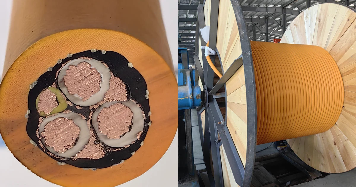
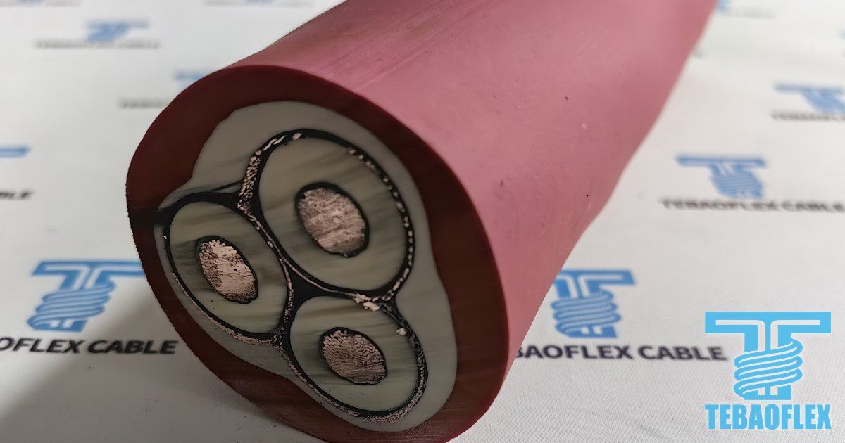
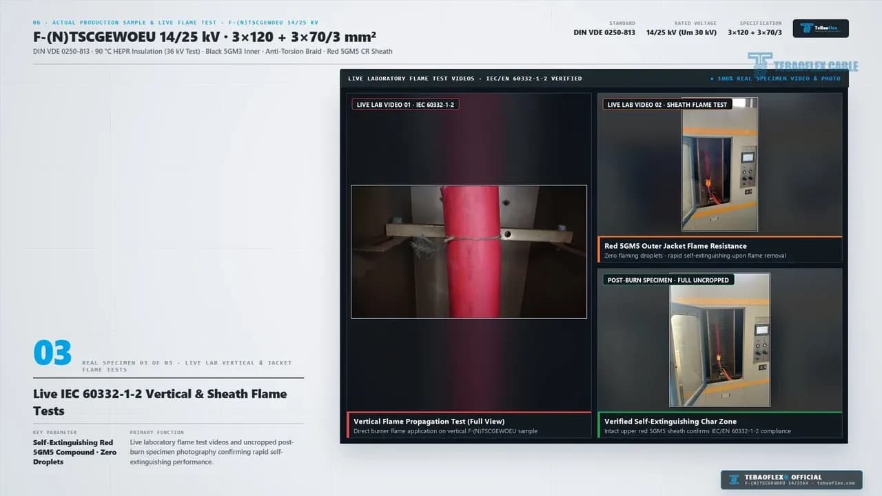
In Section 06 (0:53 to 1:03), our quality team analyzed and we tested an actual factory specimen of 14/25 kV F-(N)TSCGEWOEU 3x120+3x70/3 mm² (Date: 2026.3.14, IEC 60332-1-2 test setup, 2026). We recorded full-length sample photos, 6-core end-face cuts, and live vertical flame chamber video.
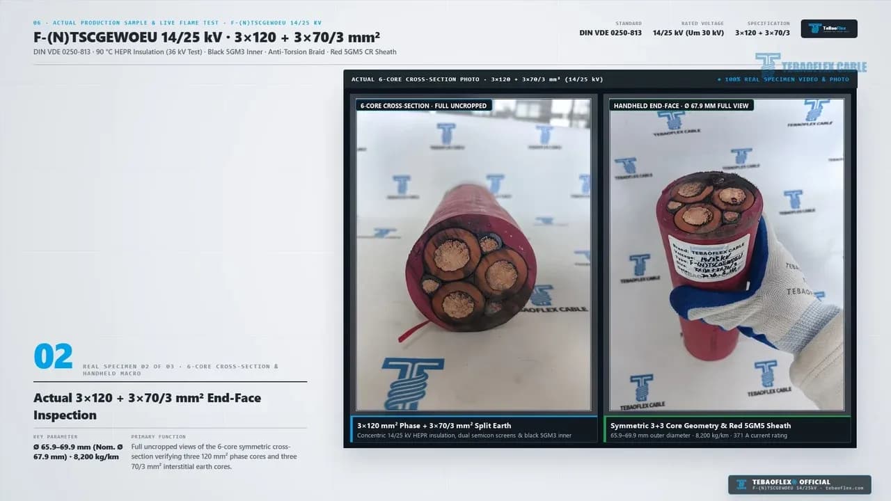
The three real panels cover the stripped sample (0:53 to 0:56), the 6-core end-face (0:56 to 0:59), and the live flame test (0:59 to 1:03). Together, they verify four physical build details.
- Handwritten 2026.3.14 QC Tag & Embossed Red 5GM5 Sheath (
0:53 to 0:56). First, Panel01 of 03shows our uncropped step-cut specimen with its QC tag (Brand: TEBAOFLEX CABLE, Voltage: 14/25 kV, Type: F-(N)TSCGEWOEU, Size: 3x120+3x70/3, Date: 2026.3.14). The red5GM5jacket shows both raised embossing14/25KV F-(N)TSCGEWOEUand crisp surface printVDE 0250-813 2026. - Concentric 120 mm² Copper & White 90 °C HEPR Wall (
0:56 to 0:59). Second, in the real end-face cut above (0:57), the three120 mm²(14.3 mm) Class 5 copper cores sit inside thick white90 °C HEPRinsulation rings. Bonded inner and strippable outer black semi-con screens bound each ring. - Symmetrical 3 x 70/3 mm² Split Earths & Black 5GM3 Bedding (
0:56 to 0:59). Third, the three23.3 mm²semi-con-covered split earth cores sit squarely in the three outer valleys. Black pressure-extruded5GM3EPR bedding fills the center and outer gussets, while white polyester braid yarns lock the sheath interface. - Live IEC/EN 60332-1-2 Vertical Flame Propagation Test (
0:59 to 1:03). Fourth, the live lab panel below (1:00) showsLIVE LAB VIDEO 01(complete cable) andLIVE LAB VIDEO 02(red5GM5outer sheath) under Bunsen burner flame per IEC 60332-1-2. ThePOST-BURN SPECIMENinset confirms rapid self-extinguishing char formation with zero flaming droplets.
How Do You Size 3x120+3x70/3 Shovel Reeling Cables (DIN VDE 0298-4)?
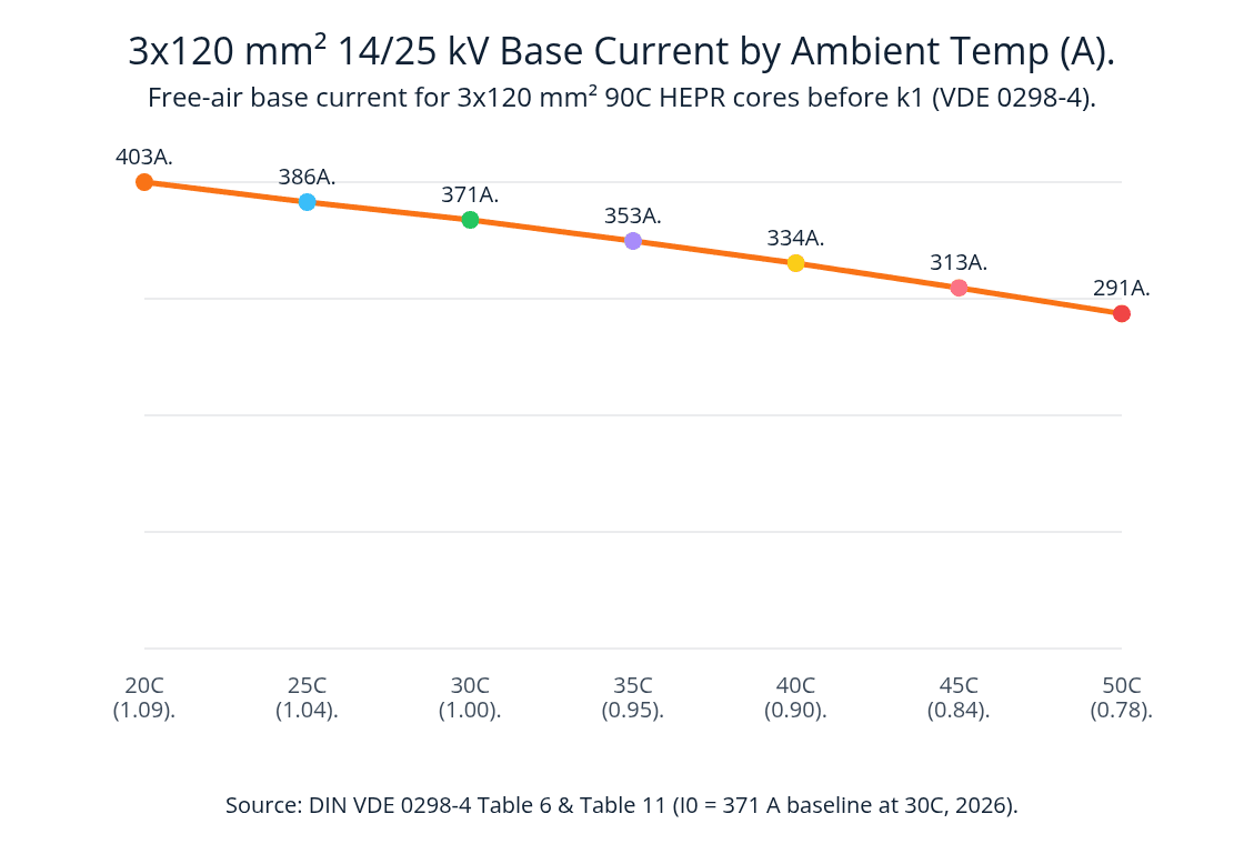
As shown at 0:10, 0:37, 0:46, and 0:49, each 120 mm² (14/25 kV) phase core has a base current (I₀) of 371 A at 30 °C in free air under DIN VDE 0298-4 (2026).
Shovel reel ampacity derating is the thermal sizing calculation under DIN VDE 0298-4 that multiplies the 30 °C baseline current (I₀ = 371 A) by a reel layer factor (k₁) and an ambient temperature factor (k₂).
Iᶻ = I₀ × k₁ × k₂.
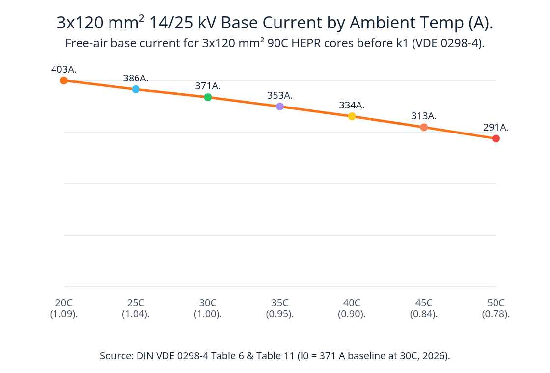
3x120 mm² 14/25 kV Base Current by Ambient Temp (A). line data: 20C (1.09) 403; 25C (1.04) 386; 30C (1.00) 371; 35C (0.95) 353; 40C (0.90) 334; 45C (0.84) 313; 50C (0.78) 291. Source: DIN VDE 0298-4 Table 6 and Table 11 (I0 = 371 A baseline, 2026).
Source: DIN VDE 0298-4 Table 6 & Table 11 MV Reeling Ampacity, 2026.
On an open bench trailing run, k₁ equals 100%. When coiled on the 295-BII shovel tail reel (0:11 to 0:18), k₁ equals 80% for 1 layer, 61% for 2 layers, 49% for 3 layers, and 42% for 4 layers (DIN VDE 0298-4, 2026).
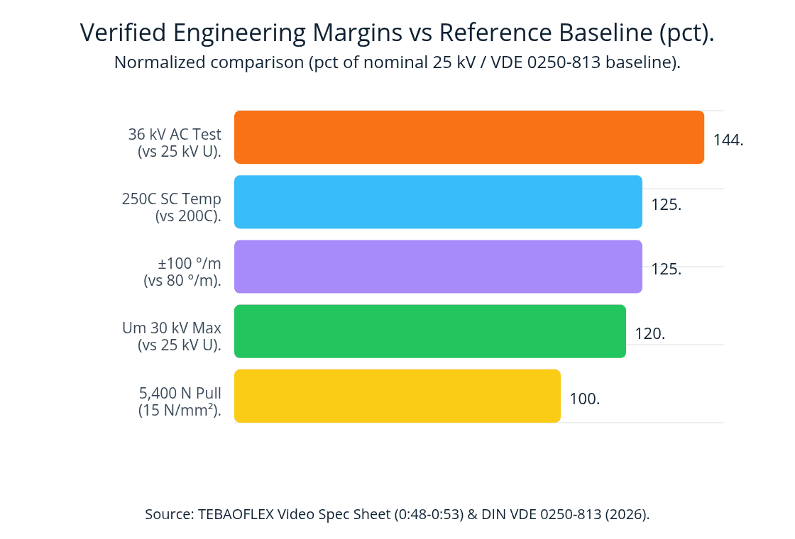
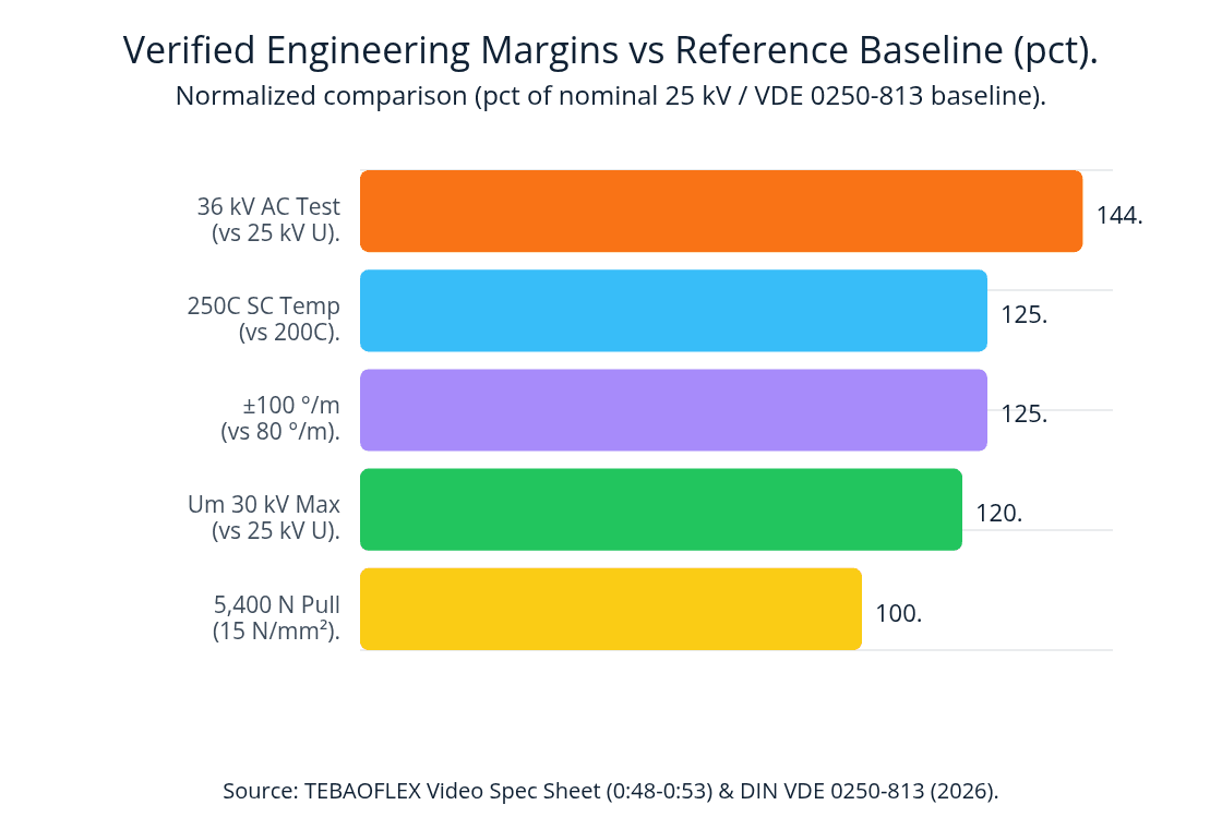
Verified Engineering Margins vs Reference Baseline (pct). Horizontal bar data: 36 kV AC Test 144. Short-Circuit Temp 125. Torsion Rating 125. Max System Um 120. Dynamic Pull 100. Source: DIN VDE 0250-813 (2026).
Source: DIN VDE 0250-813 & DIN VDE 0298-4 Engineering Ratings, 2026.
Reference Ampacity Table for 3x120+3x70/3 Shovel Reeling Cables
Consider a 25 kV open-pit electric rope shovel or dragline fed through a motorized tail reel. The table below lists continuous current limits per 120 mm² phase core under DIN VDE 0298-4 (2026).
Shovel Reeling Mode (I₀ = 371 A)
Unwound Bench Trailing (I₀ = 371 A).
- Reel Factor (k₁):
1.00 - 30 °C (k₂ = 1.00): 371.0 A (
~16.06 MVAat25 kV). - 40 °C (k₂ = 0.90): 334.0 A.
- 50 °C (k₂ = 0.78): 291.0 A.
Shovel Tail Reel: 1 Layer.
- Reel Factor (k₁):
0.80 - 30 °C (k₂ = 1.00): 297.0 A (
~12.86 MVAat25 kV). - 40 °C (k₂ = 0.90): 267.0 A.
- 50 °C (k₂ = 0.78): 233.0 A.
Shovel Tail Reel: 2 Layers.
- Reel Factor (k₁):
0.61 - 30 °C (k₂ = 1.00): 226.0 A (
~9.79 MVAat25 kV). - 40 °C (k₂ = 0.90): 204.0 A.
- 50 °C (k₂ = 0.78): 178.0 A.
Shovel Tail Reel: 3 Layers.
- Reel Factor (k₁):
0.49 - 30 °C (k₂ = 1.00): 182.0 A (
~7.88 MVAat25 kV). - 40 °C (k₂ = 0.90): 164.0 A.
- 50 °C (k₂ = 0.78): 143.0 A.
Shovel Tail Reel: 4 Layers.
- Reel Factor (k₁):
0.42 - 30 °C (k₂ = 1.00): 155.8 A (
~6.75 MVAat25 kV). - 40 °C (k₂ = 0.90): 140.3 A.
- 50 °C (k₂ = 0.78): 122.2 A.
What Should You Send Us for 14/25 kV Mining Shovel Cable Selection?
To help our team confirm the right F-(N)TSCGEWOEU build for your open-pit rope shovel, dragline, or bucket-wheel excavator, send us these 6 details.
- Shovel Model & System Voltage. State your machine model (
295-BII,495HR,P&H 4100XPC,WK-35, orWK-55), nominal bench voltage (6/10 kV,8.7/15 kV,12/20 kV,14/25 kV, or18/30 kV), and apparent power (MVA). - Phase & Split Earth Cross-Section. Confirm whether your load and fault-loop relay require 3x120+3x70/3 mm² (
371 A,17.16 kASC) or another size (3x95,3x150, or3x185 mm²). - Tail-Reel Type & Wound Layers. Specify whether your shovel uses a single-spiral monospiral tail drum or a multi-layer cylindrical drum (
1 to 4 layerswound during digging). - Tail Fairlead Radius & Pulling Torque. Share your minimum fairlead roller radius (
min bend R >= 10 x D = 680 mm) and reel drive torque setting (max pull <= 5,400 Nat15 N/mm²). - Coupler Gland & Slip-Ring Bore. Provide your substation skid coupler and collector housing gland sizes so we can verify fitment against the 65.9 to 69.9 mm outer diameter window (
67.9 mmnominal OD). - Pre-Shipment FAT & Flame Test Certificates. Let us know if you need batch test certificates (36 kV AC 5-min dielectric test,
20 °CDC resistance, and IEC/EN 60332-1-2 flame test reports) before dispatch.
Frequently Asked Questions (FAQ)
What does the designation F-(N)TSCGEWOEU 14/25 kV 3x120+3x70/3 mean under DIN VDE 0250-813?
In German VDE codes, F- and TS denote a heavy-duty guided trailing and reeling excavator cable (DIN VDE 0250-813), and (N) indicates national standard adaptation. C specifies semi-conductive field-control screens, G denotes 90 °C HEPR (3GI3) elastomer insulation, and E indicates three symmetrical split protective earth cores (3x70/3 mm²). WO specifies an anti-torsion textile braid (±100 °/m), and EU denotes a flame-retardant, oil-resistant polychloroprene (5GM5 CR/PCP) double sheath.
Why is the 70 mm² protective earth divided into three 23.3 mm² (3x70/3 mm²) split cores?
Dividing the 70 mm² ground conductor into three equal 23.3 mm² (3 x 70/3 mm²) Class 5 copper cores lets them nest symmetrically inside the three outer valleys between the 120 mm² phase cores (0:31 and 0:57). This keeps the cable round and compact (67.9 mm nominal OD), equalizes zero-sequence phase impedance, and ensures a low parallel earth-fault loop resistance of <= 0.272 Ω/km at 20 °C.
What is the continuous ampacity and 1-second short-circuit rating of the 3x120 mm² phase cores?
Under DIN VDE 0298-4 and IEC 60228, each 120 mm² Class 5 copper phase core (14.3 mm diameter, <= 0.161 Ω/km at 20 °C) carries 371 A in 30 °C free air. Because the 3GI3 HEPR insulation supports +90 °C continuous and +250 °C short-circuit temperatures, each phase core withstands a 17.16 kA 1-second short-circuit current (120 mm² x 143 A/mm²).
What is the maximum pulling force and minimum dynamic bending radius for the 67.9 mm OD cable?
Under DIN VDE 0298-4, the three 120 mm² copper phase cores (360 mm² total copper) support 15 N/mm² specific tensile stress, yielding a maximum dynamic pulling force of 5,400 N (~550 kgf) and ±100 °/m torsional stability (0:49). The minimum dynamic bending radius over shovel tail fairlead rollers and drum barrels is R >= 10 x D (680 mm).
Does the 70-second video show real production sample footage and live flame testing?
Yes. The 70-second video includes 100% real factory specimen photos and live IEC/EN 60332-1-2 flame test footage (0:00 to 0:03 and 0:53 to 1:03, TEBAOFLEX Log, 2026). It also features schematic 3D 295-BII shovel and cutaway animations (0:03 to 0:53). The real footage verifies our stripped sample (Date: 2026.3.14), the 6-core 3x120+3x70/3 end-face (0:57), and live vertical flame chamber self-extinguishing performance (1:00).
Request a Specification Check or Custom 14/25 kV Shovel Cable Quote
Planning an open-pit electric rope shovel cable replacement, dragline feeder upgrade, or 25 kV mine bench project with 14/25 kV (Uₘ 30 kV) TEBAOFLEX F-(N)TSCGEWOEU 3x120+3x70/3 mm²? Please contact our engineering team or browse our Reeling Cable Catalog and Mining & Tunneling Cable Solutions to get a routine 36 kV test report and quote.
Contact TEBAOFLEX on WhatsApp: +86 185 9591 3361