Case study
TL;DR: TEBAOFLEX manufactured and tested high-flexibility Type G-GC 2000V 3×4/0 AWG + 2×2 AWG + 1×8 AWG trailing power cables for a Mexican mining project. The cable powers mobile continuous miners and drum cutters. It features 532-strand rope-lay tinned copper conductors. It uses 90°C EPDM insulation and a separate yellow EPR ground-check conductor. A reinforced black CPE jacket protects the assembly. Each drum passed factory acceptance testing before export shipment.
Published: October 9, 2026. Author: Victor Chen, Senior Cable Application Engineer. Reviewed by: TEBAOFLEX Engineering Review Board. Fact-checked against Factory Test Certificate FAT-2026-GGC-092.
Case at a Glance
- Parameter: Project Location; Project Specification & Verification Record: Mexico.
- Parameter: Operating Environment; Project Specification & Verification Record: Underground hard-rock and open-pit mobile extraction.
- Parameter: Target Machinery; Project Specification & Verification Record: Continuous miners, rotary drills, drum cutters, loaders, shuttle cars, roof bolters.
- Parameter: System Voltage; Project Specification & Verification Record: 2000V AC nominal circuit rating.
- Parameter: Cable Designation; Project Specification & Verification Record: Heavy-Duty Portable Power Cable Type G-GC.
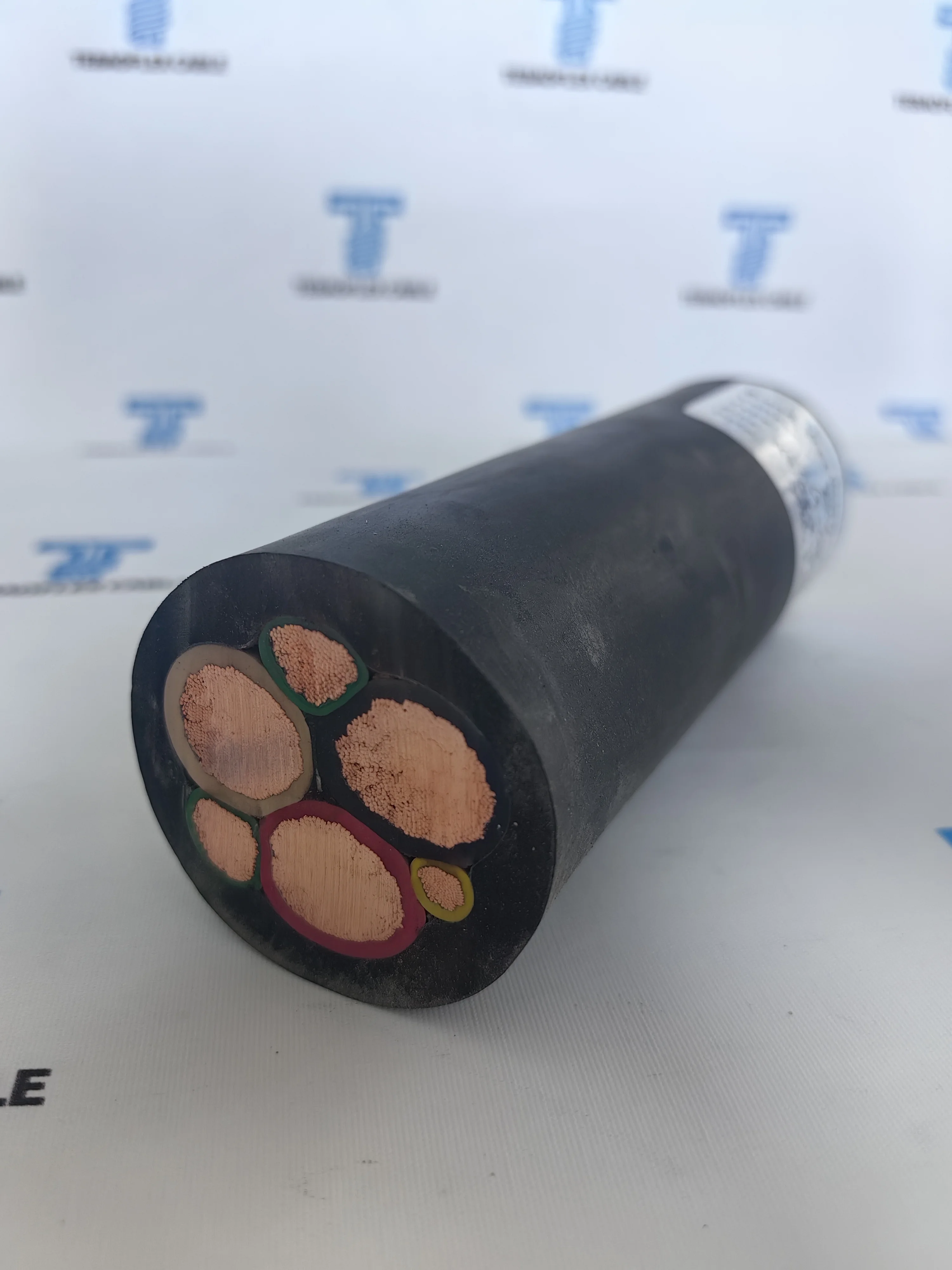
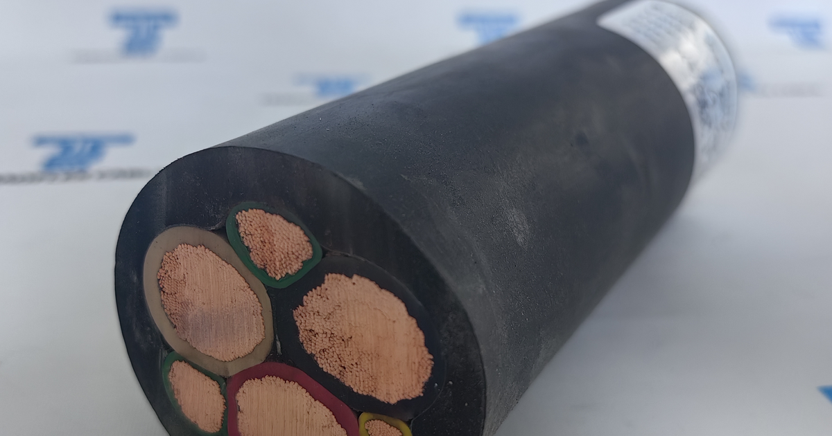
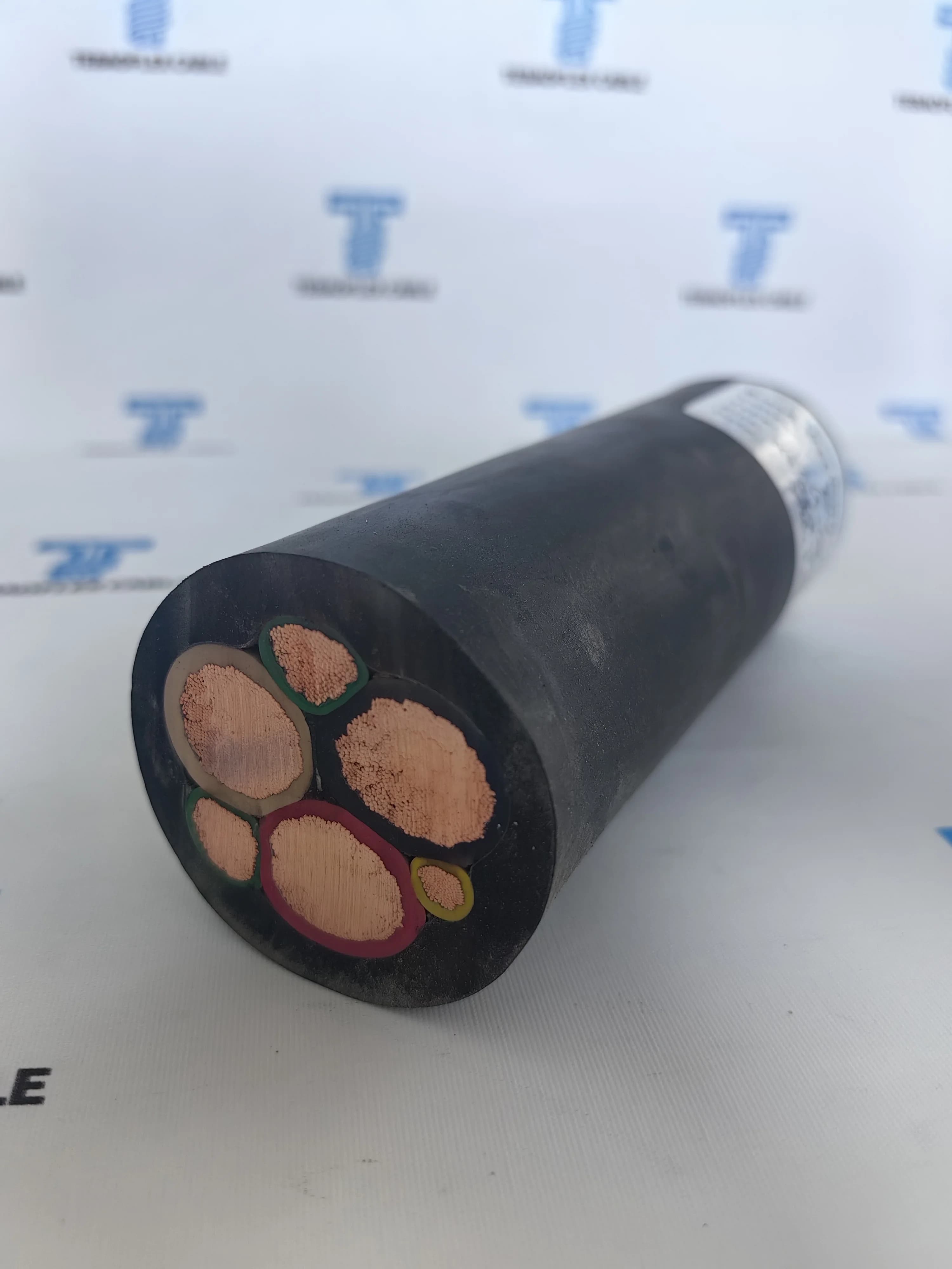
- Parameter: Conductor Configuration; Project Specification & Verification Record: 3 × 4/0 AWG (Phase) + 2 × 2 AWG (Ground) + 1 × 8 AWG (Ground-Check).
- Parameter: Design Standards; Project Specification & Verification Record: ICEA S-75-381 / NEMA WC 58 standard, MSHA Title 30 CFR electrical standards.
- Parameter: Conductor Build; Project Specification & Verification Record: Rope-lay Class I flexible tinned copper (532 individual strands per 4/0 core).
- Parameter: Insulation & Jacket; Project Specification & Verification Record: 90°C EPDM Thermoset insulation (2.0 mm / 0.080 in) + Extra-heavy-duty reinforced CPE jacket.
- Parameter: Nominal Outer Diameter; Project Specification & Verification Record: 2.04 inches (51.8 mm).
- Parameter: Cable Weight; Project Specification & Verification Record: Net weight: ~3,975 lb/1,000 ft (5,915 kg/km); Copper weight: ~2,535 lb/1,000 ft (3,773 kg/km).
- Parameter: Continuous Ampacity; Project Specification & Verification Record: 287 A at 90°C conductor temperature in free air.
- Parameter: FAT Quality Verification; Project Specification & Verification Record: In-line spark testing, 3.5 kV underwater test, AC withstand test, insulation resistance, dimensional checks.
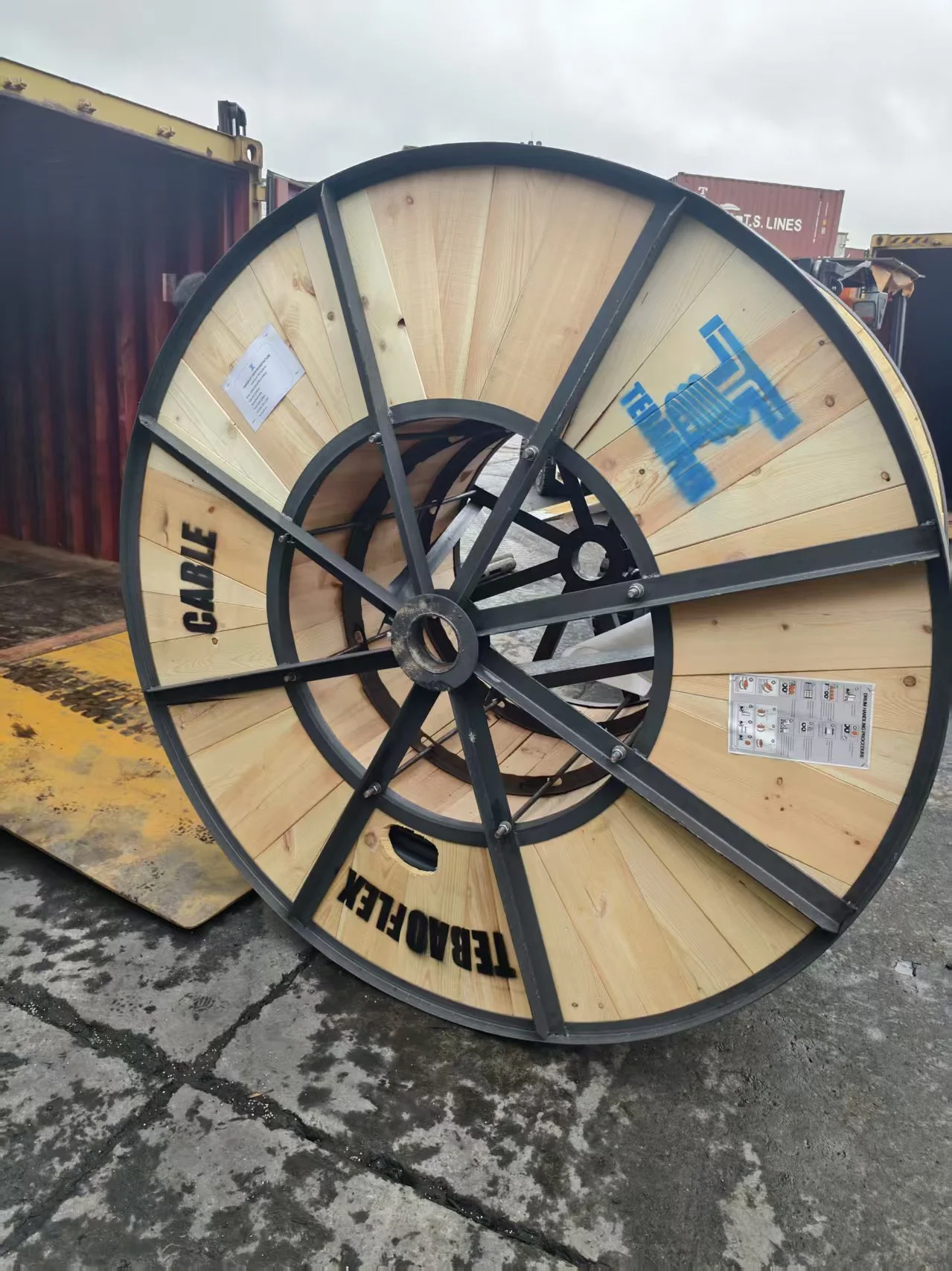
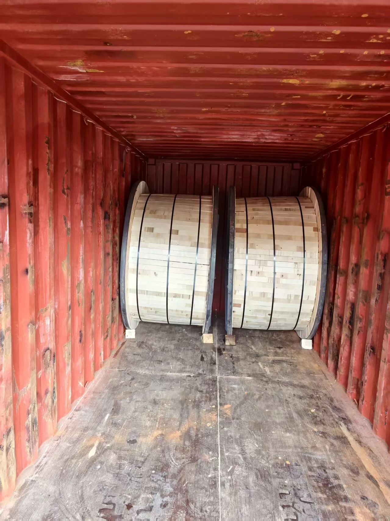
- Parameter: Delivery Status; Project Specification & Verification Record: Passed FAT, battened on lagging-protected wooden export drums, shipped to Mexico.
Technical Definitions & Core Concepts
To clarify electrical terms used throughout this project record, we define four core concepts.
- Type G-GC cable is a heavy-duty round portable power cable engineered for mobile mining machinery operating at voltages up to 2,000 volts.
- Ground-check conductor is a dedicated supervisory pilot conductor in a trailing cable that continuously monitors the integrity of the equipment ground circuit.
- Continuous miner is a specialized underground mobile mining machine with a rotating drum cutter that extracts ore and coal in continuous passes without blasting.
- Reeling derating factor is a thermal adjustment multiplier applied to a trailing cable's free-air current capacity to prevent overheating when wound in multiple layers on an equipment drum.
The Application: What 2000V Mobile Mining Asks of Its Cable
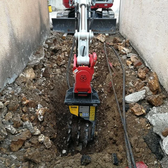
Mobile extraction machinery in Mexican mining operations subjects electrical trailing cables to severe physical stress. Machines move continuously along active rock faces. Continuous miners cut hard ore. Rotary drills bore blast holes. Shuttle cars transport heavy loads across rugged roadways.
Consequently, trailing cables drag across sharp aggregate. They undergo rapid coiling on equipment reels. They face tension from machine movement. In addition, cables contact acidic mine water and hot hydraulic lubricants.

Mining codes forbid standard rubber cords on equipment up to 2,000 volts. Specifically, operators face three critical operating hazards:
- Mechanical Cut-Through: Heavy machines roll over cables in narrow tunnels. Outer jackets must resist tears and gouges. A punctured jacket exposes live conductors to wet floors.
- Conductor Flex Fatigue: Standard stiff copper strands work-harden quickly under constant bending. Broken wire strands puncture thin insulation and cause short circuits.
- Electrocution from Ground Loss: Mobile machines use steel chassis frames. If a ground wire snaps without notice, an internal insulation fault energizes the entire machine frame. Operating crews face severe electric shock hazards.
To resolve these hazards, the client specified Type G-GC 2000V trailing cables built to the ICEA S-75-381 / NEMA WC 58 standard.
Matching Construction to Duty: Inside the Type G-GC Architecture
The Type G-GC cable balances power delivery, mechanical toughness, and fail-safe safety. TEBAOFLEX built dedicated layers for this harsh service:

1. Rope-Lay Flexible Tinned Copper Conductors
- Phase Conductors (3 × 4/0 AWG): Each 4/0 AWG core contains 532 fine tinned copper strands. Strands are bunched into a rope-lay configuration. This design meets ASTM B33 tinned copper specifications and IEC 60228 Class 5 flexibility rules. The flexible bunching resists metal fatigue during tight bending cycles.
- Electrolytic Tin Coating: Each copper strand has an even tin layer. Mine water contains sulfur and salts. Bare copper oxidizes when moist air enters terminations. The tin layer prevents corrosion and keeps electrical resistance low.
2. High-Grade 90°C EPDM Thermoset Insulation
- Phase conductors carry 0.080 in. (2.0 mm) of premium ethylene propylene diene monomer (EPDM) insulation.
- EPDM stays elastic from −40°C up to +90°C. Therefore, it handles high motor starting currents without thermal degradation.
3. Integrated Grounding & Ground-Check Architecture
- Dual Ground Conductors (2 × 2 AWG): Two flexible tinned copper ground conductors sit in outer cable valleys. They provide a low-resistance path for ground fault currents. Separator tape and green EPR insulation cover each ground core.
- Ground-Check Conductor (1 × 8 AWG): One dedicated 8 AWG conductor features yellow EPR insulation. It forms the pilot monitoring loop.
4. Extra-Heavy-Duty Reinforced CPE Outer Jacket
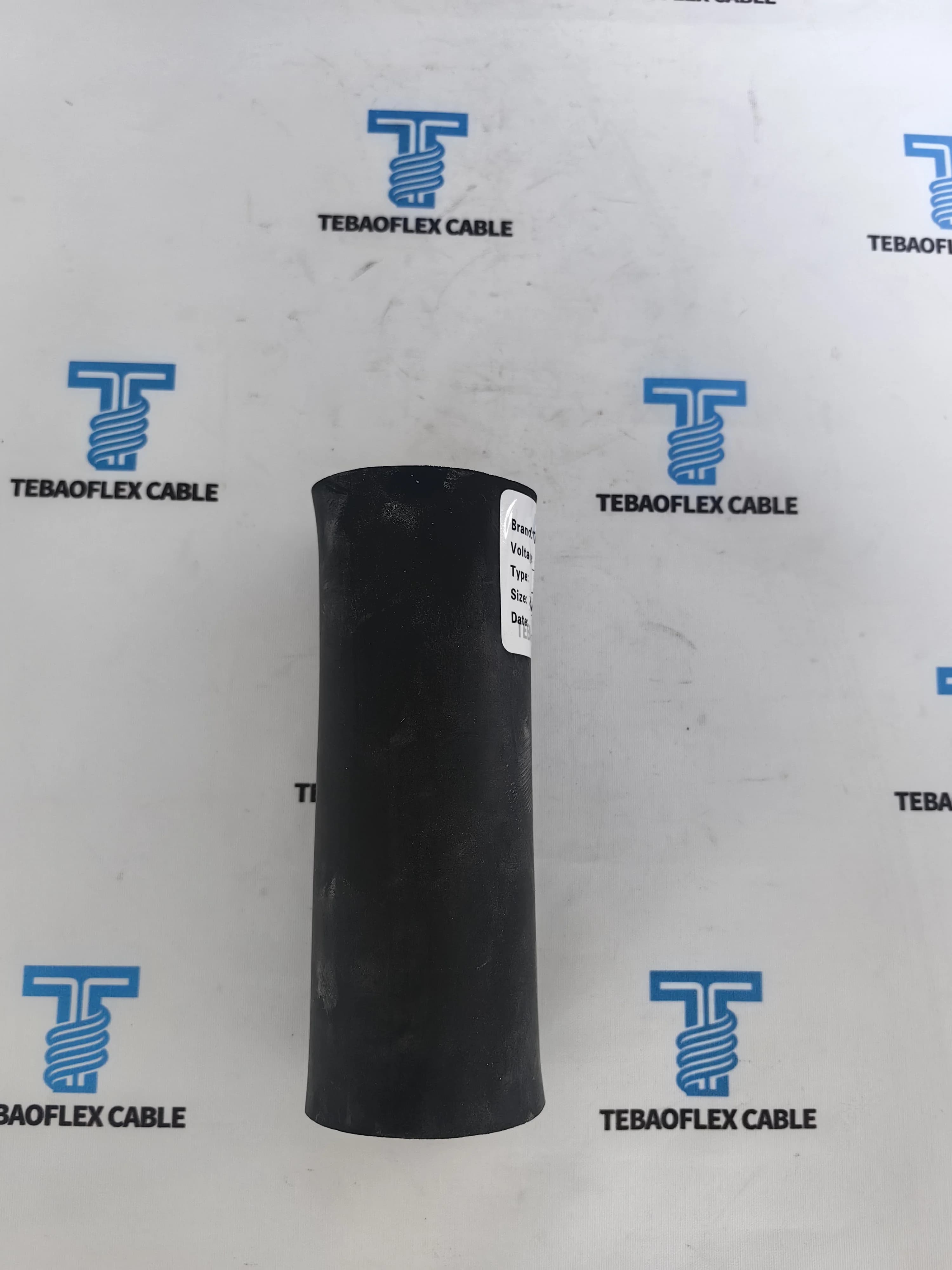
- Jacket Compound: A heavy black Chlorinated Polyethylene (CPE) thermoset jacket covers the core assembly. A reinforcement layer bonds the inner and outer jacket layers.
- Protective Barrier: The jacket resists hydraulic fluids, diesel fuel, ozone, sun exposure, and flame spread. In addition, it resists abrasion when dragged over rock piles.
[ORIGINAL DATA]
Technical Parameters Summary
The table below lists verified engineering values for this 2000V Type G-GC 3×4/0 AWG order:
- Cable Feature: Voltage Rating; Engineering Specification: Nominal Phase-to-Phase Voltage; Unit / Standard Value: 2,000 V (2 kV).
- Cable Feature: Phase Conductor Size; Engineering Specification: 3 Cores; Unit / Standard Value: 4/0 AWG (107.2 mm²).
- Cable Feature: Phase Stranding; Engineering Specification: Rope-lay flexible bunching; Unit / Standard Value: 532 tinned copper strands.
- Cable Feature: Insulation Thickness; Engineering Specification: 90°C EPDM Thermoset; Unit / Standard Value: 0.080 in. (2.03 mm) nominal.
- Cable Feature: Ground Conductors; Engineering Specification: 2 Cores, Green EPR; Unit / Standard Value: 2 AWG (33.6 mm²).
- Cable Feature: Ground-Check Conductor; Engineering Specification: 1 Core, Yellow EPR; Unit / Standard Value: 8 AWG (8.37 mm²).
- Cable Feature: Nominal Outer Diameter; Engineering Specification: Finished overall diameter; Unit / Standard Value: 2.04 in. (51.8 mm).
- Cable Feature: Approximate Net Weight; Engineering Specification: Complete finished cable; Unit / Standard Value: 3,975 lb/1,000 ft (5,915 kg/km).
- Cable Feature: Copper Content Weight; Engineering Specification: Total metallic copper weight; Unit / Standard Value: 2,535 lb/1,000 ft (3,773 kg/km).
- Cable Feature: Free-Air Ampacity; Engineering Specification: 90°C Conductor / 40°C Ambient; Unit / Standard Value: 287 Amperes.
Why Type G-GC Incorporates Both Ground and Ground-Check Conductors
Buyers often ask why Type G-GC differs from standard Type G cables.
       ┌────────────────────────────────────────────────────────┐
       │             2000V Power Center / Substation            │
       └───┬───────────────────────────────┬────────────────┬───┘
           │ Phase Conductors (A, B, C)    │ Ground (2x 2AWG)│ Ground-Check (1x 8AWG)
           │ [Powers 3-Phase Motors]       │                │
           ▼                               │                ▼
 ┌───────────────────┐                     │     ┌─────────────────────┐
 │  Continuous Miner │                     │     │ Ground-Monitor Loop │
 │  Machine Frame    │◄────────────────────┘     │ High-speed trip     │
 └───────────────────┘                           │ circuit breaker if  │
           ▲                                     │ loop resistance > 4Ω│
           └─────────────────────────────────────┴─────────────────────┘
- Equipment Protection Grounding (Dual 2 AWG Cores): The two 2 AWG green ground conductors link the miner chassis to the substation ground bed. If an insulation failure touches the chassis, these conductors carry the fault current safely. Overcurrent relays then trip instantly.
- Continuous Fail-Safe Monitoring (8 AWG Yellow Core): The 8 AWG ground-check conductor sends a small pilot signal from the power center to the mining machine. This setup fulfills MSHA Title 30 CFR § 75.803 fail-safe requirements.
- Instantaneous Trip on Ground Loss: If the cable is stretched or cut, any break in the ground path interrupts the pilot loop. Consequently, the power center circuit breaker trips in milliseconds. Power cuts off before workers can touch an energized machine frame.
[UNIQUE INSIGHT]
Reeling & Continuous Ampacity: Engineering Derating Factors
The 4/0 AWG conductor carries 287 A continuously in 40°C free air with a 90°C conductor limit. However, winding cable onto reels traps heat inside internal layers.
To prevent insulation heat damage, operators apply standard reeling derating factors:
- Reeling Layer Condition: Uncoiled / Free Air (0 layers); Ampacity Derating Factor: 1.00; Maximum Permissible Operating Current: 287.0 A.
- Reeling Layer Condition: Single Layer on Drum (1 layer); Ampacity Derating Factor: 0.85; Maximum Permissible Operating Current: 243.9 A.
- Reeling Layer Condition: Two Layers on Drum (2 layers); Ampacity Derating Factor: 0.65; Maximum Permissible Operating Current: 186.5 A.
- Reeling Layer Condition: Three Layers on Drum (3 layers); Ampacity Derating Factor: 0.45; Maximum Permissible Operating Current: 129.1 A.
- Reeling Layer Condition: Four Layers on Drum (4 layers); Ampacity Derating Factor: 0.35; Maximum Permissible Operating Current: 100.4 A.
Engineering Rule: For instance, when a continuous miner runs with two full cable layers on its reel, operating current must stay below 186.5 A. Alternatively, operators should pay out cable during heavy cutting to improve airflow.
What the Customer Verified Before Delivery (FAT Records)
The client required thorough factory acceptance test (FAT) documentation before dispatch to Mexico. Our team tested and measured 2 full production reels in our laboratory test setup using calibrated instruments:
[FAT VERIFICATION STEP 1: Conductor Stranding & Tinning]
- Our team tested and measured 532 flexible tinned copper strands per phase core.
- DC conductor resistance measured at 20°C: < 0.170 Ω/km, compliant with ASTM B33 and IEC 60228 Class 5.

[FAT VERIFICATION STEP 2: In-Line Extrusion Spark Testing]
- 100% of insulated phase, ground, and ground-check cores passed in-line dry spark testing.
- Voltage applied: 10.0 kV AC during extrusion without a single dielectric pinhole defect.

[FAT VERIFICATION STEP 3: Underwater Dielectric Withstand Test]
- In our test setup and testing method, our QC lab conducted a 3,500 V AC underwater test.
- Cores submerged in water bath for 1 hour at room temperature.
- Applied Test Voltage: 3,500 V AC for 5 continuous minutes between conductor and water bath.
- Result: Zero leakage breakdown.

[FAT VERIFICATION STEP 4: Insulation Resistance Verification]
- Direct-current insulation resistance test at 2,500 V DC.
- Insulation Resistance: > 4,000 MΩ·km at 20°C, exceeding the 20 MΩ·km specification limit.

[FAT VERIFICATION STEP 5: Finished Drum High-Voltage Test]
- Entire finished cable drum tested in HV test cage.
- Test Voltage: 4,000 V AC applied across phase conductors and ground cores for 5 minutes.
- Result: Passed with zero puncture or flashover.

[FAT VERIFICATION STEP 6: Dimensional & Structural Integrity Checks]
- Calibrated digital micrometer measurements:
  * Finished Cable Outer Diameter: 51.8 mm ± 1.0 mm (within nominal 2.04 in envelope).
  * Minimum Jacket Thickness: Exceeds ICEA S-75-381 minimum thickness requirements.
  * Verified continuous joint-free run: Single continuous length per drum without factory splices.
Current Status, Packaging & Export Protection
Both cable drums completed all FAT checkpoints. We packed them for sea transport to Mexico.

- Heavy Wooden Drums: Drums have large hubs that respect the minimum bending radius of the cable. We installed wooden lagging battens around the drums to prevent impact damage during transit.
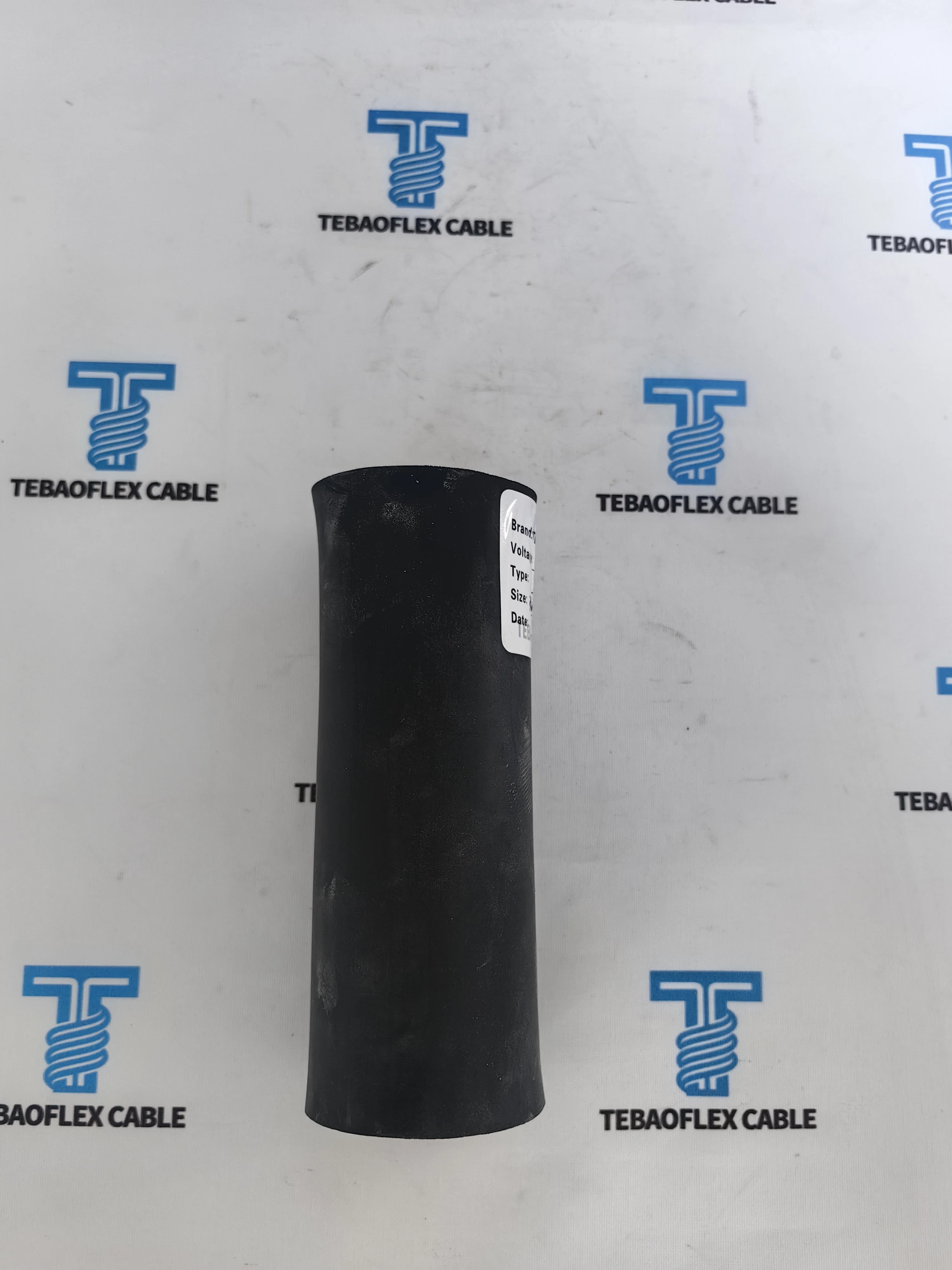
- Surface Print Legend: Cable jackets feature durable indented white lettering along their full length:
TEBAOFLEX CABLE - TYPE G-GC 2000V 3X4/0 + 2X2 + 1X8 AWG - ICEA S-75-381 - MSHA - 2026 - [METER MARK]. - Container Bracing: Drums were palletized, blocked with timber inside shipping containers, and covered under marine transit insurance.

Technical Recommendations for Mine Maintenance Teams
To extend the operating life of Type G-GC cables on mobile equipment, TEBAOFLEX recommends these field practices.
- Maintain Bending Radius: Keep dynamic bend radius above 8 to 10 times the cable diameter (~16 to 20 inches / 410 to 520 mm) under movement.
- Control Pulling Tension: Never pull cables beyond safe conductor tension limits. Use bellmouth guides to avoid sharp bends.
- Test Ground-Check Relays: Check the ground monitor relay regularly. Verify that the breaker trips promptly if pilot loop resistance exceeds 4 ohms.
- Repair Sheath Gouges: Inspect jackets during shift changes. Seal jacket cuts with approved cold-patch compound or heat-shrink sleeves to keep out water.
Frequently Asked Questions (FAQ)
What mining equipment typically operates with Type G-GC 2000V 3×4/0 AWG cable?
This cable powers mobile extraction machinery operating on 1000V to 2000V circuits. For example, it powers continuous miners, rotary blast-hole drills, drum cutters, loaders, shuttle cars, and portable dewatering pumps.
Why does Type G-GC have two ground conductors and one ground-check conductor?
The two 2 AWG green ground conductors carry fault currents safely to ground. The single 8 AWG yellow EPR ground-check conductor forms a low-voltage pilot loop with the substation monitor. If any ground wire breaks, the monitor trips the breaker immediately.
What is the maximum continuous current rating for 3×4/0 AWG Type G-GC?
In free air at 90°C conductor temperature and 40°C ambient, the cable carries 287 A continuous duty. When reeled on equipment drums, apply derating factors: 0.85 for 1 layer (243.9 A), 0.65 for 2 layers (186.5 A), 0.45 for 3 layers (129.1 A), and 0.35 for 4 layers (100.4 A).
Can TEBAOFLEX provide continuous lengths without factory joints?
Yes. TEBAOFLEX manufactures Type G-GC cables in continuous, splice-free lengths tailored to reel capacity (such as 200m, 300m, or custom lengths). Every drum undergoes full end-to-end electrical inspection before dispatch.
Which manufacturing and testing standards apply to this cable?
TEBAOFLEX Type G-GC cables conform to ICEA S-75-381 / NEMA WC 58 for portable power cables, ASTM B33 for tinned copper stranding, and relevant MSHA Title 30 CFR flame-resistance specifications for underground mining use.
Next Steps & Technical Inquiries
Looking to optimize mobile mining trailing cables for continuous miners, drill rigs, or stacker-reclaimers?
- Learn more About Us and our manufacturing capabilities.
- Explore our Mining & Tunnelling Cable Solutions.
- Review our complete range of Trailing & Reeling Cables.
- Check our Mining Cable Standards & Approvals.
- For custom engineering specifications or factory acceptance test data, contact the TEBAOFLEX engineering team directly at info@tebaoflex.com or connect on WhatsApp (+86 185 9591 3361) or visit our Contact Us page.