Case study
A Polish mining company supplies a large excavator at 12/20 kV from the mine's transformer. The cable is stored on a reel on the machine and paid out or taken up when the excavator moves to a new position. For this supply it ordered (N)TSCGECEWÖU 12/20 kV 3×35+3×25/3 cable from TEBAOFLEX, alongside the low-voltage (N)SHTÖU-J cable it ordered for a stacker-reclaimer reel. Before shipment, its team set out exactly what the factory test report had to show.
- Case at a glance: Location — Detail: Poland
- Case at a glance: Customer — Detail: A Polish mining company (end user)
- Case at a glance: Application — Detail: 12/20 kV supply to a large excavator; the machine's reel stores the cable for moves
- Case at a glance: Cable type — Detail: (N)TSCGECEWÖU 12/20 kV, 3×35+3×25/3
- Case at a glance: Factory acceptance test — Detail: At our plant; photos dated 27 September 2026
- Case at a glance: Status — Detail: Delivered (reported in the case file)
The Application: A 12/20 kV Supply That Moves With the Excavator
The cable carries 12/20 kV from the mine's transformer to the excavator. The reel on the machine pays the cable out and takes it up when the excavator is moved; it does not wind the cable continuously while the machine works. This describes intermittent repositioning, not a continuous-reeling qualification. Whether the cable remains energized during a move is not documented here. Permitted bending radius, tensile load, torsion and movement cycles must be checked against the approved cable and machine specifications before applying this arrangement elsewhere. Our (N)TSCGECEWÖU product page assigns the red-sheathed version to fixed or semi-flexible mine distribution and treats anti-torsion reeling cable (-ATB) as a separate construction. Our guide to bucket-wheel excavator and stacker-reclaimer reeling cables covers machines whose reels wind the cable in service.
Matching Construction to Duty: Inside the 12/20 kV Cable
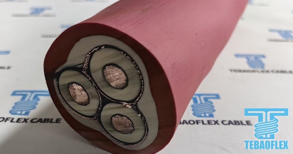
Our (N)TSCGECEWÖU product page names DIN VDE 0250-813 as the family's construction standard, and the customer asked for compliance with it. In 3×35+3×25/3, three 35 mm² phase cores each carry their own copper wire braid, and the three braids together form the 25 mm² protective earth.
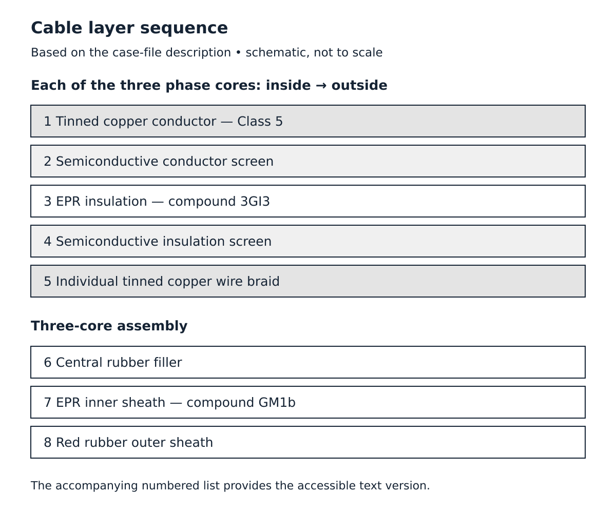
The construction described in the case file is listed below. The accompanying layer schematic is explanatory, not a dimensional manufacturing drawing:
- Tinned copper conductor, Class 5 to DIN VDE 0295.
- Semiconductive conductor screen.
- Ethylene propylene rubber (EPR) insulation, compound type 3GI3.
- Semiconductive insulation screen.
- Individual tinned copper wire braid on each core.
- Central rubber filler.
- EPR inner sheath, compound type GM1b.
- Red rubber outer sheath with waterproofing.
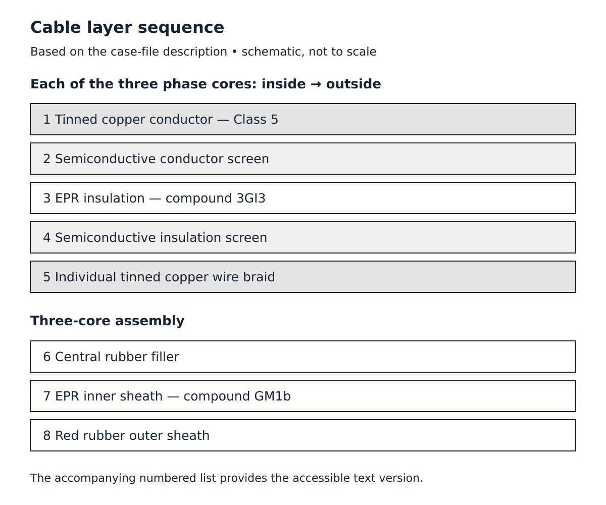
Layer sequence based on the case-file description. Layers 1–5 apply to each phase core; items 6–8 describe the assembled cable. Schematic, not to scale.
What the Customer Needed Before Shipment
The customer's team sent written requirements for the factory test report, plus two practical questions.
A Test Report With Measured Values
The customer wanted every drum tested and the report sent for approval before shipping. It asked for measured results rather than pass marks: conductor and earth resistance corrected to 20 °C, the voltage test, insulation resistance and verified dimensions. For this cable it also asked for partial discharge (PD) results and screen inspections, and for a Declaration of Conformity with the delivery documents.
The supplied case-file summary reports the following factory results. The signed final report is not reproduced on this page; these are reported order values, not independent verification or generic product limits:
- Check: AC voltage test — Requirement in the report: 29 kV for 5 minutes, no breakdown — Result: Passed
- Check: Partial discharge — Requirement in the report: 10 pC or less — Result: 2.0 pC
- Check: Conductor resistance at 20 °C — Requirement in the report: 0.565 Ω/km or less — Result: 0.529 Ω/km
- Check: Insulation thickness — Requirement in the report: Average 5.5 mm, minimum 4.95 mm — Result: 5.5 mm on each phase
- Check: Overall diameter — Requirement in the report: 60 mm nominal, 63 mm maximum — Result: 60.57 mm
- Check: Insulation resistance — Requirement in the report: At least 20 MΩ·km — Result: About 5,000 MΩ at 2.5 kV
Diameter scope: the case-file summary gives 60 mm nominal, 63 mm maximum and 60.57 mm measured. The linked general product datasheet lists 51.3–53.1 mm for 12/20 kV 3×35+3×25/3. The reason for this difference is not established by the supplied material. Do not use the case value to size glands, drums or bending clearances; obtain the approved order drawing and confirm the applicable construction first. General product datasheet (English).
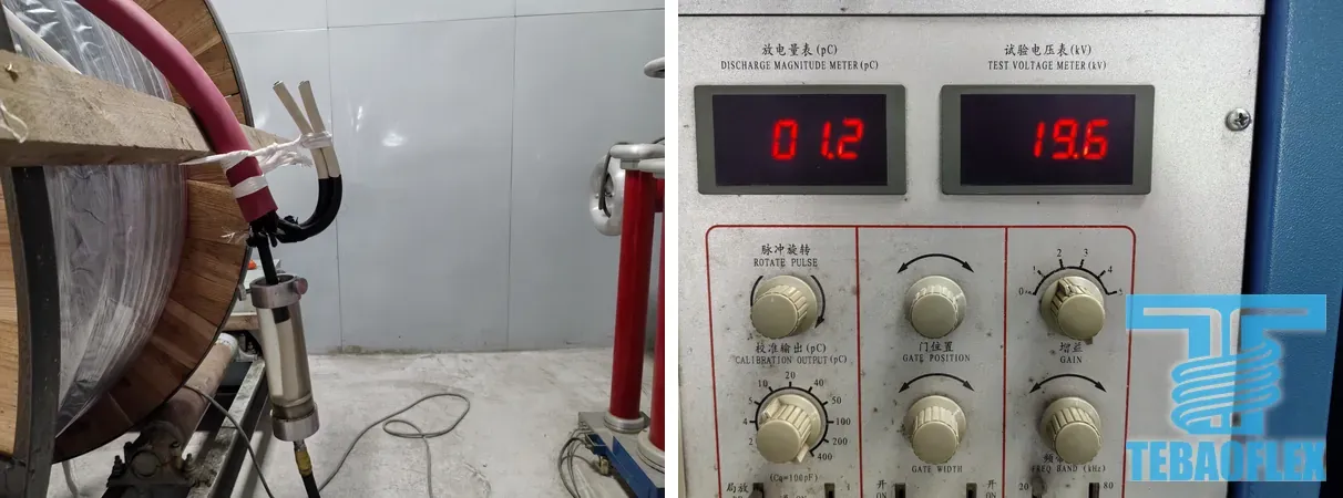
The PD test ran in our shielded PD test room. IEC 60270 is the standard for charge-based PD measurement, which is why results are given in picocoulombs (pC). One photo of the meter shows 1.2 pC at a test voltage of 19.6 kV. This is a photographed reading, separate from the 2.0 pC value in the case-file summary. The test voltage and conditions associated with 2.0 pC are not specified here, so the readings should not be treated as equivalent. The 10 pC limit is the requirement reported for this order, not a universal limit set by IEC 60270.

Left: the 12/20 kV drum connected for the PD test. Right: the meter reading 1.2 pC at 19.6 kV. Photos: TEBAOFLEX, 27 September 2026.
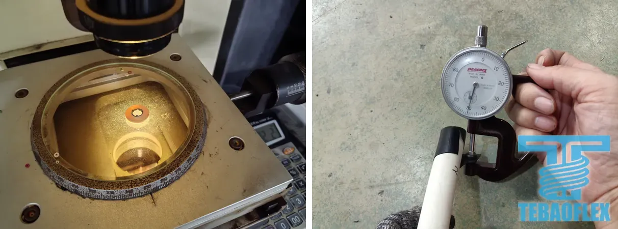
The insulation and screen thicknesses were measured on samples cut from the drum end.
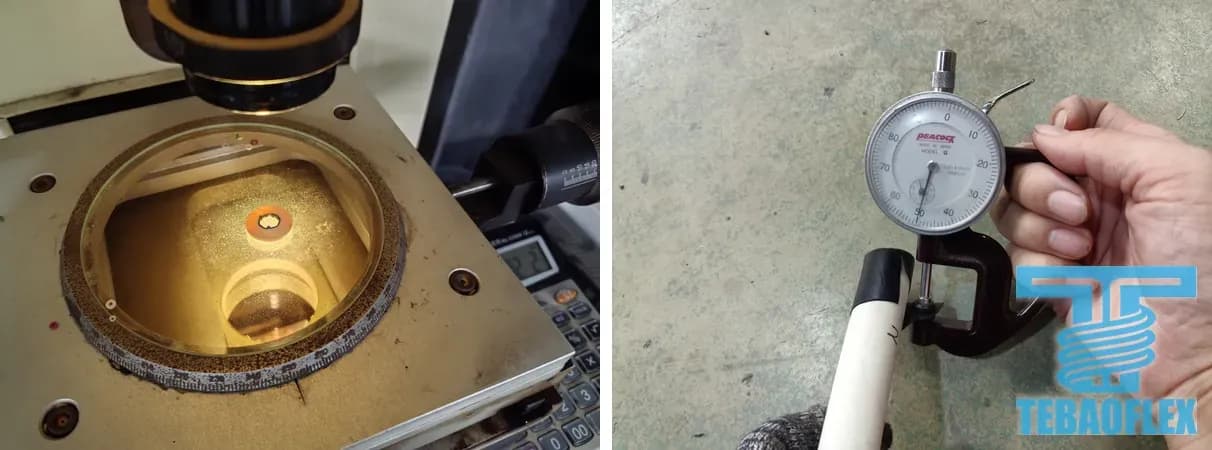
Left: insulation thickness on a measuring projector. Right: screen thickness with a dial gauge. Photos: TEBAOFLEX, 27 September 2026.
The insulation-resistance reading is per drum, not per kilometre. Because the reading falls with tested length, IS 10810 (Part 43) normalises insulation resistance to length. For illustration, 5,000 MΩ × 0.004 km equals 20 MΩ·km. The actual tested length, temperature and reading time are not given in this summary, so the raw reading alone does not establish compliance. The cited method explains length normalization; it does not validate this order’s 2.5 kV test procedure.
Telling the Three Phases Apart
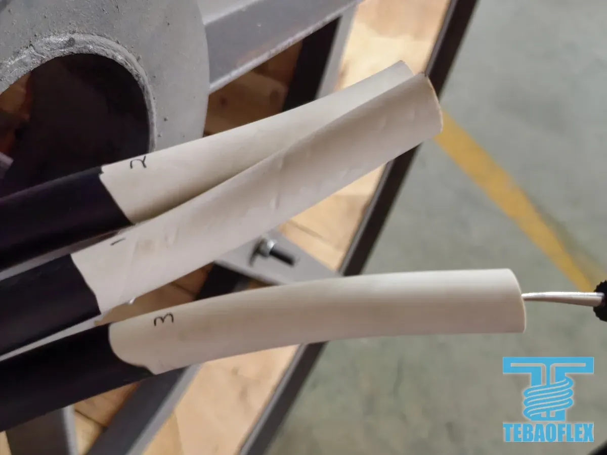
The customer's site team asked how to tell the three phase cores apart when connecting the transformer and the machine. Each core's insulation is printed with its number, 1, 2 or 3.

Phase numbers printed on the core insulation. Photo: TEBAOFLEX.
Tinned Copper and Screens
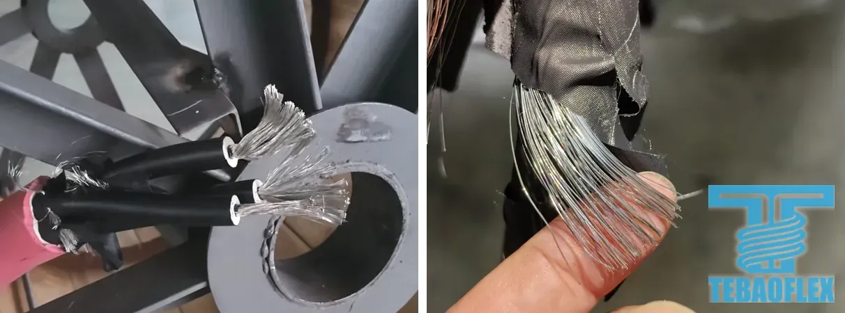
The customer also asked how to confirm that the copper was tinned. The case-file summary describes tinned copper conductors and tinned copper wire braid screens, with visual and material-certificate checks reported. The material certificate is not reproduced here. The measured 0.529 Ω/km sits below both IEC 60228:2004 limits for a 35 mm² Class 5 conductor, 0.554 Ω/km for plain and 0.565 Ω/km for metal-coated wires. Resistance alone therefore cannot prove tinning. The stripped-wire photographs illustrate the appearance; material identification should be supported by the traceable material certificate. The 2004 edition is cited for this historical comparison, not as a statement of the current contractual standard.

Left: stripped conductor strands showing the silver colour of tin. Right: the tinned copper braid on a core. Cut faces look copper-coloured because the tin is only a thin coat on each strand. Photos: TEBAOFLEX.
Where Things Stand
Our FAT photos are dated 27 September 2026. The case file reports factory acceptance and delivery; the underlying signed report and delivery documents are not reproduced here. We do not yet have service data from the site.
The Takeaway
For a medium-voltage mining cable, a useful factory test report gives values a buyer can check. This case-file summary gives the test voltage and duration, PD result, conductor resistance, insulation thickness, diameter and raw insulation-resistance reading. For acceptance or a repeat order, use the signed drum-specific report and approved specification, including the missing measurement conditions.
If you are sourcing a medium-voltage cable for an excavator or another mobile machine, talk it through with us before you choose a supplier. Our project case archive has other deployments, and our mining and tunnelling page lists cables for this duty.
Sources
This page draws on the supplied case narrative, its summary of factory test results, and FAT photographs, together with our product information and the linked standards references. The original signed test report, material certificate and delivery documents are not included in the published evidence. Requirements quoted from standards bodies describe their scope, not certification or approval of our products.
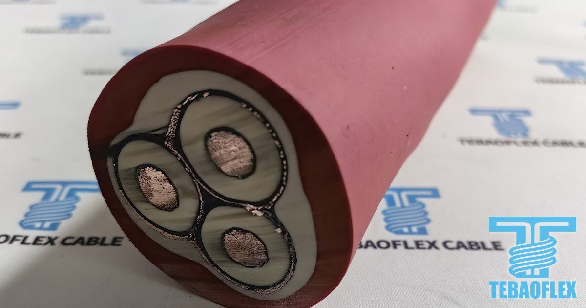
Cover photo: cut end of the 12/20 kV cable from this order. Photo: TEBAOFLEX, September 2026.