What the video shows
An 82-second overview of the 2 kV IEEE 1580 Type P 1111 MCM cable, combining workshop sample footage with schematic offshore top-drive and four-layer construction animations.
The video illustrates a sample, process, or operating context. Final product construction, suitability, standards, and test acceptance criteria are confirmed against the ordered specification.
By TEBAOFLEX Jyen. Updated on October 24, 2026.
The web video is 1080p/60fps. Use the full-size image and chart links to inspect details.
TL;DR: This 82-second (1:22) video inspects our TEBAOFLEX® 2kV IEEE 1580 Type P · 1111 MCM (1C x 562 mm²) submersible offshore cable built to IEEE 1580 (2026) and UL 1309. It pairs two live 1.0x factory specimen videos and eight uncropped workshop photos (0:00 to 0:03,0:08 to 0:14,0:44 to 0:51, and1:10 to 1:16) with schematic 3D rig and 4-layer cutaway animations. Inside the 44.9 mm (1.77 in) cable, a2,745 / 24 AWGClass I rope-lay tinned copper core (ASTM B33) carries 1,150 A in 40 °C free air. A2.9 mm90 °CEPR wall passes a 13.5 kV AC 5-minute test, while a2.4 mmblackXL-CPEjacket supportsR >= 8 x OD(359 mm) bending and ±180 °/m torsion.
On semi-submersible offshore drilling rigs (KRISTIN 6406/2 class), jack-up units, and drillships, single-core top-drive and mud-pump feeders must deliver 2,000 V (2 kV) VFD power (1,150 A per core) through hanging derrick service loops. At the same time, they must survive ester-based drilling mud, saltwater immersion, and continuous vertical stroke flexing down to 359 mm (8 x OD). This video page examines our 2kV IEEE 1580 Type P 1111 MCM (1C x 562 mm²) cable across an 82-second walkthrough. It covers the live 1:1 optical macro end-face check, the 4-layer strip-back, and the white dot-matrix sheath print. Below, you can watch the full video, check the timestamp log, review IEEE 45 ampacity derating tables, and use our top-drive loop checklist.
What Happens in Each Scene of the 82-Second Product Video?
The 82-second video combines two visual formats so marine electrical engineers can verify both offshore derrick loop routing and real workshop build quality. First, it shows live 1.0x factory specimen videos and uncropped sample photos (0:00 to 0:03, 0:08 to 0:14, 0:44 to 0:51, and 1:10 to 1:16). Second, it shows schematic 3D semi-submersible rig (KRISTIN 6406/2) and 4-layer CAD cutaway animations (0:03 to 0:08, 0:14 to 0:44, and 0:51 to 1:10). The table below logs every scene by timestamp.
Timestamp
0:00 - 0:03
- Video Scene & Visual Mode: Opening Cover Card (Real sample + 3D rig)
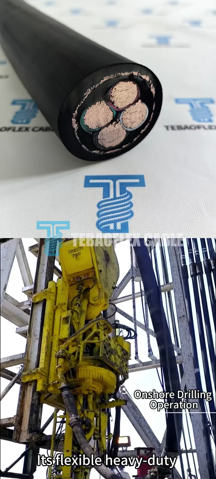
- Key Technical Details Shown on Screen: Shows our real black
1111 MCMsample printedTEBAOFLEX Submersible 1111 MCM 1C Type P 2kV IEEE 1580 (2001)over a semi-submersible rig
0:03 - 0:08
- Video Scene & Visual Mode: 01 / Cross-Section Reveal (Schematic 2D/3D)
- Key Technical Details Shown on Screen: Reveals the
1C x 562 mm²(37rope-lay sub-bundles) core, helical separator tape,90CEPR wall, and blackXL-CPEjacket
0:08 - 0:14
- Video Scene & Visual Mode: 01B / Live Specimen End-Face (Live 1.0x video)
- Key Technical Details Shown on Screen: Shows
LIVE FACTORY VIDEO 01 OF 02(1.0xnatural speed, zero crop) with a1:1optical macro loupe over the2,745 / 24 AWGcut face (44.9 mmOD)
0:14 - 0:17
- Video Scene & Visual Mode: 02 / Offshore Rig Scene: Step 01 (Schematic 3D)
- Key Technical Details Shown on Screen: Shows
Semi-Submersible Offshore Drilling Rig (KRISTIN 6406/2)powered by a2000V IEEE 1580 TYPE PVFD system
0:17 - 0:20
- Video Scene & Visual Mode: 02 / Switchgear to Loop: Step 02 (Schematic 3D)
- Key Technical Details Shown on Screen: Labels
1. 2000V VFD Switchgear Room,2. Marine Ladder Tray & Hanging Service Loop(SS316), and3. TOP DRIVE (2000V VFD MOTOR)
0:20 - 0:24
- Video Scene & Visual Mode: 02 / Top-Drive Stroke Flex: Step 03 (Schematic 3D)
- Key Technical Details Shown on Screen: Highlights
3 x 1111 MCM Type Phanging loop flexing atR >= 8xOD (359 mm)and2000 V / 1,150 Aduring vertical top-drive travel
0:24 - 0:27
- Video Scene & Visual Mode: 02 / 3D X-Ray Cutaway: Step 04 (Schematic 3D)
- Key Technical Details Shown on Screen: Zooms into the hanging loop to reveal the
2,745 / 24 AWGtinned copper core,90CEPR, and blackXL-CPEmud/oil jacket (-40Ccold rating)
0:27 - 0:44
- Video Scene & Visual Mode: 03 / 4-Layer Strip-Back (04 to 01) (3D CAD cutaway)
- Key Technical Details Shown on Screen: Strips back
04 Black XL-CPE(2.4 mm),03 90C EPR(2.9 mm,13.5 kVtest),02 Separator Tape, and01 Class I Tinned Cu(33.7 mmOD)
0:44 - 0:51
- Video Scene & Visual Mode: 03B / Live Sheath Print & QC Tag (Live 1.0x video)
- Key Technical Details Shown on Screen: Shows
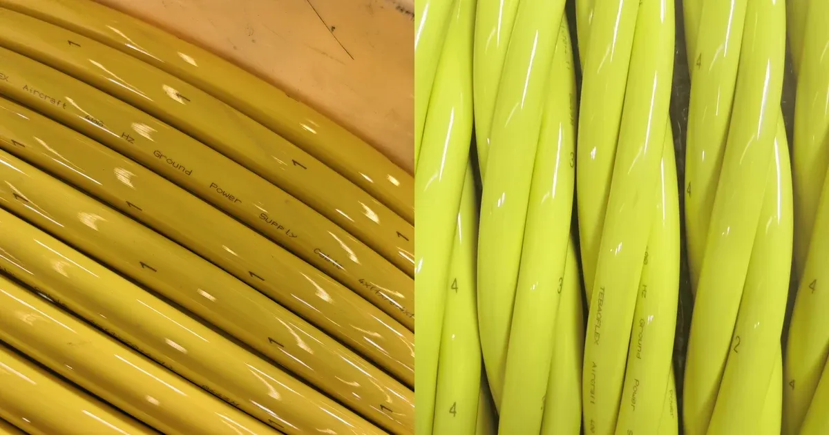
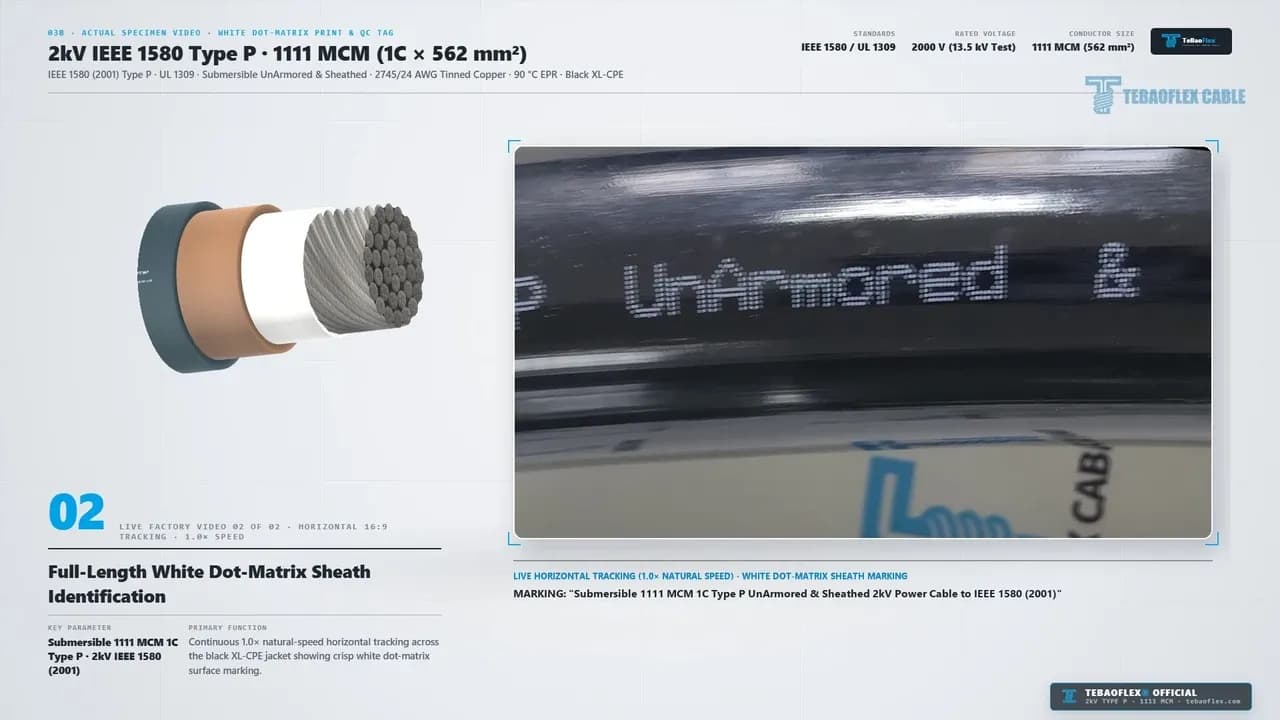
LIVE FACTORY VIDEO 02 OF 02horizontal tracking of the white dot-matrix legend"Submersible 1111 MCM 1C Type P..."and blue QC tag
0:51 - 1:04
- Video Scene & Visual Mode: 04 / 3D & 2D Construction Summary (Schematic 3D/2D)
- Key Technical Details Shown on Screen: Combines all 4 layer callouts (
01 to 04), a1C x 562 mm²concentric cross-section (44.9 mmOD), and a 4-row wall thickness table
1:04 - 1:10
- Video Scene & Visual Mode: 05 / Key Technical Specifications (Engineering card)
- Key Technical Details Shown on Screen: Lists
2000 V (13.5 kV test),1111 MCM (2745w),FT4 & Mud-Resistant,8xOD ±180 °/m,+90C / -40C Cold, and44.9 mm (6,298 kg/km)
1:10 - 1:16
- Video Scene & Visual Mode: 06 / Real Sample Photos (01 to 08) (Real photos)
- Key Technical Details Shown on Screen: Displays two 4-photo grids (
REAL SPECIMEN 01 & 02) of uncropped standing samples, macro end-faces, four batch samples, and floor legends
1:16 - 1:22
- Video Scene & Visual Mode: Closing Brand Card (Graphic summary card)
- Key Technical Details Shown on Screen: Displays
Jiangsu Tebaoflex Special Cable Co., Ltd.contact info (Publisher: TeBaoFlex Jyen,info@tebaoflex.com,+86 185 9591 3361)
Video Scope Note: TheKRISTIN 6406/2semi-submersible drilling rig,2,000 VVFD switchgear room,SS316ladder tray, hanging top-drive loop, and 4-layer strip-back animations (0:03 to 0:08,0:14 to 0:44, and0:51 to 1:10) are schematic 3D engineering views. They are not offshore field footage and are not to scale. Uncropped1.0xlive factory specimen videos and real workshop sample photos appear at0:00 to 0:03,0:08 to 0:14,0:44 to 0:51, and1:10 to 1:16. All electrical, thermal, and mechanical values represent official ratings under IEEE 1580, UL 1309, ASTM B33, and IEEE 45.
Video at a Glance: Video & Sample Technical Summary
The table below lists the verified specifications shown in the video and defined by IEEE 1580 (2026) and UL 1309.
Parameter
Commercial Model Designation
- Verified Video & Standard Specification:
TEBAOFLEX 2kV IEEE 1580 Type P · 1111 MCM (1C x 562 mm²)Submersible UnArmored & Sheathed Power Cable
Actual Sheath Legend (0:44 to 0:51)
- Verified Video & Standard Specification:
"Submersible 1111 MCM 1C Type P UnArmored & Sheathed 2kV Power Cable to IEEE 1580 (2001)"
Reference Standards
- Verified Video & Standard Specification: IEEE 1580 Type P, UL 1309 Marine, ASTM B33 / B172 Class I, IEEE 1202 / CSA FT4
Rated & Test Voltage
- Verified Video & Standard Specification: 2,000 V (2 kV) continuous VFD rating; factory 5-minute AC dielectric withstand test at 13,500 V (13.5 kV)
Conductor (Layer 01)
- Verified Video & Standard Specification: 1111 MCM (562 mm²) Class I flexible tinned copper, 2,745 strands of 24 AWG (
0.51 mm) in37rope-lay bundles (33.7 mm OD)
Separator Tape (Layer 02)
- Verified Video & Standard Specification: Non-hygroscopic helical paper / polyester separator tape over the
37rope-lay tinned copper sub-bundles
Primary Insulation (Layer 03)
- Verified Video & Standard Specification: 90 °C flame-retardant cross-linked EPR (0.115 in / 2.9 mm nominal wall,
-40 °Cto+90 °Cwet/dry)
Outer Jacket (Layer 04)
- Verified Video & Standard Specification: Heavy-duty black cross-linked chlorinated polyethylene (XL-CPE, 0.095 in / 2.4 mm wall, submersible, oil & mud resistant)
OD, Weight, Ampacity & Bending
- Verified Video & Standard Specification: 44.9 mm (1.77 in) nominal OD; 6,298 kg/km (
4,232 lb/1,000 ft); 1,150 A at 40 °C free air; min bendR >= 8 x OD(359 mm), ±180 °/m torsion
How Does the Video Illustrate Semi-Submersible Rig Top-Drive Loops?
An IEEE 1580 Type P offshore power cable is a flame-retardant, oil-resistant, and drilling-mud-resistant marine power cable built for fixed offshore platforms, FPSOs, and mobile offshore drilling units (IEEE 1580, 2026). It pairs a finely stranded ASTM Class I tinned copper core with cross-linked 90 °C EPR insulation and a thermoset XL-CPE outer jacket.
In Section 02 (0:14 to 0:27), a four-step 3D sequence shows how three parallel 1111 MCM (562 mm²) single-core Type P feeders power a reciprocating derrick top drive on a semi-submersible rig (KRISTIN 6406/2).
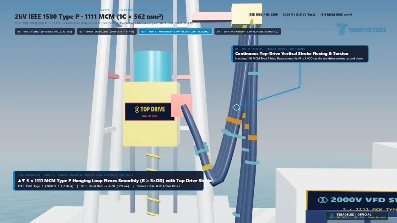
- Semi-Submersible Drilling Rig VFD Grid (
0:14 to 0:17). First, the clip shows theKRISTIN 6406/2offshore platform operating a2,000 Vvariable-frequency drive (VFD) bus for its derrick top drive and mud pumps. - Switchgear Room to Marine Ladder Tray (
0:17 to 0:20). Second, the3 x 1111 MCM Type Pfeeders exit1. 2000V VFD Switchgear Roomand run across open deckSS316stainless ladder trays (2. Marine Ladder Tray & Hanging Service Loop) up the derrick mast. - Top-Drive Hanging Loop Stroke Flexing (
0:20 to 0:24). Third, as shown at0:21above, the free-hanging catenary loop flexes smoothly atR >= 8 x OD(359 mm). It absorbs ±180 °/m torsion while carrying 2,000 V / 1,150 A to the2000V VFD MOTOR. - 3D X-Ray Cutaway Inside the Service Loop (
0:24 to 0:27). Finally, a 3D X-ray view inside the flexing loop highlights the2,745 / 24 AWGtinned copper bundles. It also shows the90 °CEPR wall and-40 °Cmud-resistant blackXL-CPEjacket.
An offshore derrick top-drive service loop is a suspended catenary cable assembly that transfers 2,000 V VFD power and control signals from a fixed derrick standpipe clamp to the vertically traveling top-drive drilling motor.
For example, when a top-drive carriage strokes 30 to 40 meters up and down the derrick guide rails, the hanging cable loop rolls continuously through a 359 mm radius. At the same time, it is splashed with ester-based drilling mud and salt spray. Stiff Class B (61-wire or 91-wire) conductors quickly work-harden and snap under this cyclic fatigue. To explore related dynamic power feeders, see our marine and offshore cable catalog, our F-(N)TSCGEWOEU 14/25kV 3x120+3x70/3 shovel reeling cable video, and our 6/10kV (N)TSCGEWOEU+FO fiber-optic crane reeling cable video.
How Is the 2kV IEEE 1580 Type P · 1111 MCM Cable Constructed?
In Section 03 (0:27 to 0:44) and Section 04 (0:51 to 1:04), the video strips back our 2kV IEEE 1580 Type P 1111 MCM cable. It progresses from the black outer jacket (Layer 04) down to the 33.7 mm tinned copper core (Layer 01).
Cross-linked chlorinated polyethylene (XL-CPE) is a thermoset elastomer jacket compound cured into a three-dimensional polymer network that resists aromatic oils, ester-based drilling muds, saltwater submergence, and vertical tray flame propagation (Engineering ToolBox, 2026).
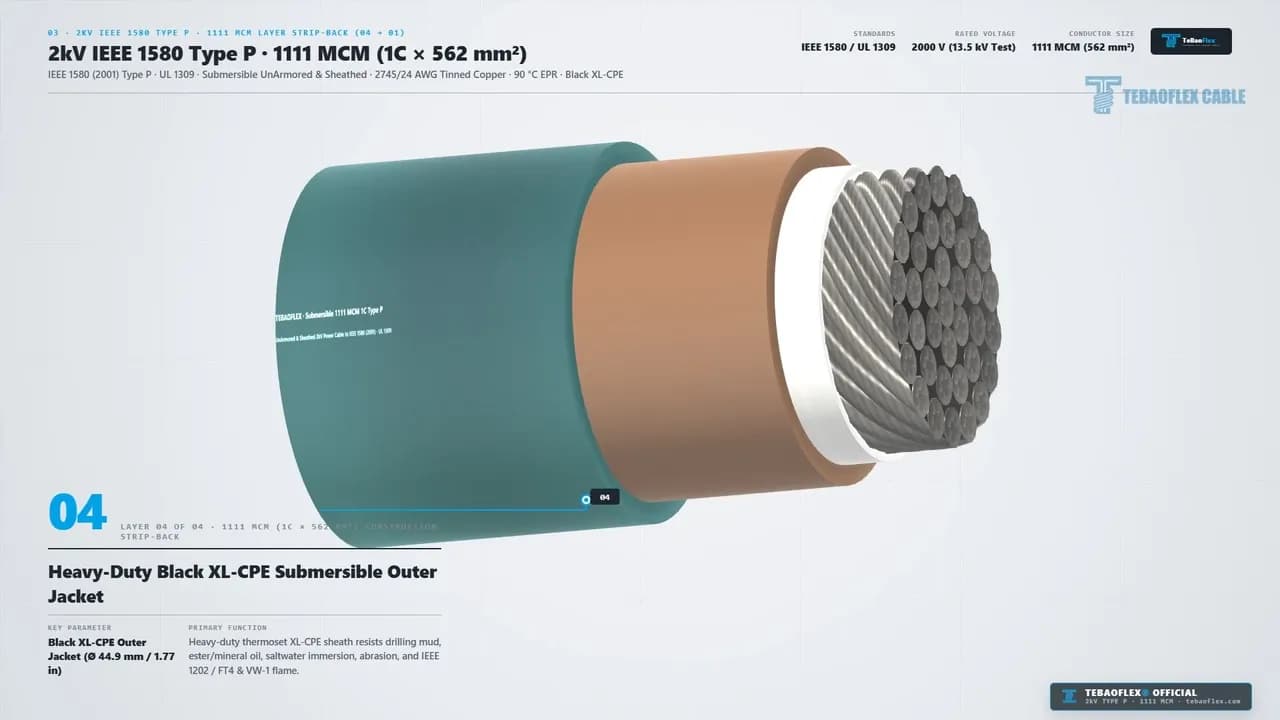
Layer 04: Heavy-Duty Black XL-CPE Submersible Outer Jacket (0:27 to 0:31)
The outer protective sheath (Layer 04) uses a 0.095 in (2.4 mm) wall of heavy-duty black XL-CPE extruded to a nominal overall diameter of 44.9 mm (1.77 in). Formulated to IEEE 1580 Type P and UL 1309, it resists calcium bromide brines, oil-based mud (OBM), ester synthetic fluids, and continuous saltwater submergence. It also passes IEEE 1202 / CSA FT4 vertical tray flame tests (70,000 BTU/hr) and UL 2556 VW-1 flame testing.
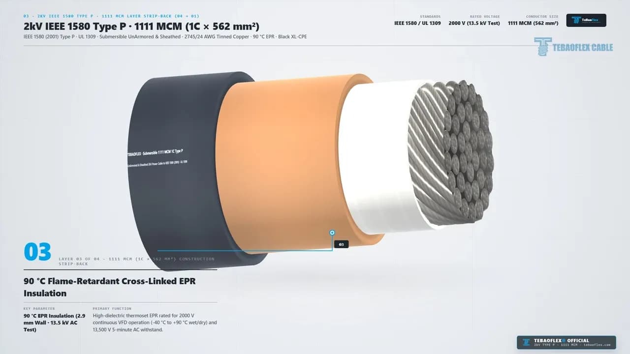
Layer 03: 90 °C Flame-Retardant Cross-Linked EPR Insulation (0:31 to 0:35)
Beneath the black XL-CPE sheath sits Layer 03, a 0.115 in (2.9 mm) wall of 90 °C flame-retardant cross-linked ethylene propylene rubber (EPR) per IEEE 1580 Type E/P. Although rated for 2,000 V (2 kV) service, every finished reel length passes a 13,500 V (13.5 kV) AC 5-minute dielectric withstand test (675% of rated voltage, UL 1309, 2026). This high dielectric margin absorbs 2,000 V PWM inverter dV/dt voltage reflections across -40 °C arctic cold to +90 °C wet or dry operation (+250 °C short-circuit).
Layer 02 & Layer 01: Helical Separator Tape & 2,745 / 24 AWG Class I Tinned Copper (0:35 to 0:44)
Under the EPR wall, Layer 02 wraps a non-hygroscopic helical paper / polyester separator tape around Layer 01, the 1111 MCM (562 mm²) conductor (33.7 mm / 1.33 in diameter).
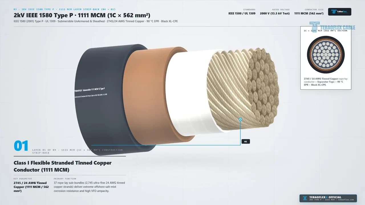
Instead of stiff concentric stranding, Layer 01 combines 2,745 strands of 24 AWG (0.51 mm) annealed tinned copper grouped into 37 rope-lay sub-bundles per ASTM B33 and ASTM B172 Class I. Each wire's tin coating stops salt-fog corrosion and rubber vulcanization blackening. Meanwhile, the Layer 02 separator tape keeps extruded EPR out of the strand interstices so the 37 sub-bundles slip smoothly during 359 mm (8 x OD) bending and strip cleanly during lug crimping.
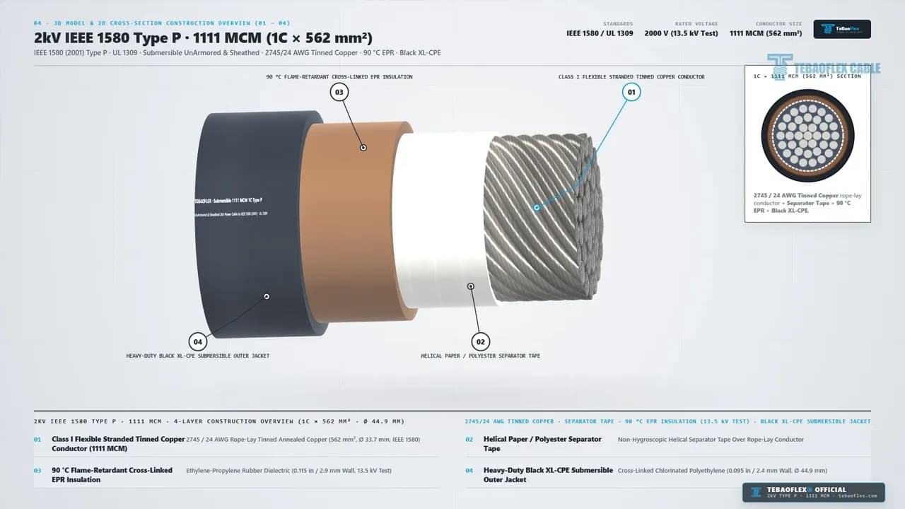
Layer No
Layer 01
- Structural Component: 1111 MCM (
562 mm²) Core - Material & Wall Specification:
2,745 / 24 AWG(37bundles, 33.7 mm OD, ASTM B33) - Primary Offshore Engineering Function: Carries 1,150 A (
40Cfree air) and flexes at8 x ODwithout strand fatigue
Layer 02
- Structural Component: Helical Separator Tape
- Material & Wall Specification: Non-hygroscopic paper / polyester tape (
34.3 mmOD) - Primary Offshore Engineering Function: Allows low-friction bundle slip during flexing and residue-free lug stripping
Layer 03
- Structural Component: 90 °C EPR Insulation
- Material & Wall Specification: Cross-linked flame-retardant EPR (0.115 in / 2.9 mm wall)
- Primary Offshore Engineering Function: Passes 13.5 kV AC 5-min test (
-40Cto+90Cwet/dry) for2,000 VVFD spikes
Layer 04
- Structural Component: Black XL-CPE Outer Jacket
- Material & Wall Specification: Thermoset
XL-CPE(0.095 in / 2.4 mm wall, 44.9 mm OD) - Primary Offshore Engineering Function: Resists ester drilling mud, oil, saltwater submergence, and
IEEE 1202 FT4flame
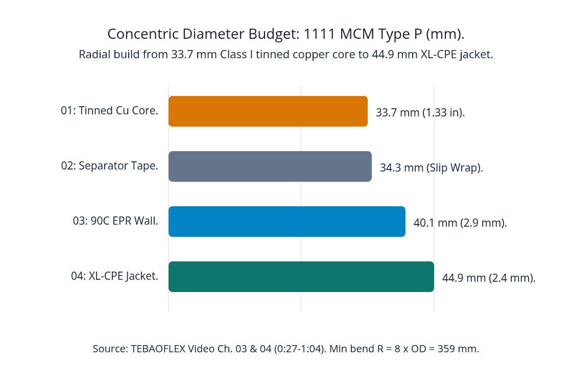
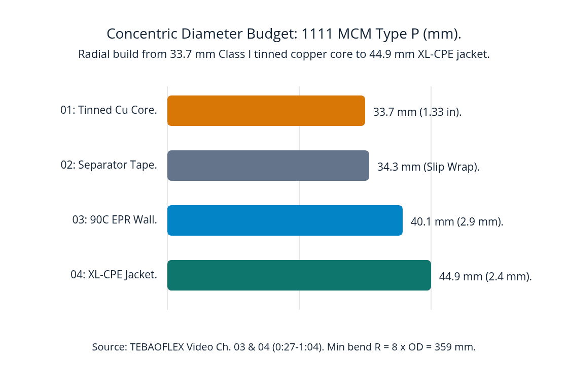
Cumulative outer diameter in mm across Layer 01 Tinned Copper Core (33.7 mm), Layer 02 Separator Tape (34.3 mm), Layer 03 90C EPR Insulation (40.1 mm), and Layer 04 Black XL-CPE Jacket (44.9 mm). Source: TEBAOFLEX Video Chapters 03 and 04 (2026).
Figure 1: Concentric radial build of the TEBAOFLEX 2kV IEEE 1580 Type P 1111 MCM (1C x 562 mm²) power cable per IEEE 1580 Type P, 2026.
What Do the Live Factory Videos (01B & 03B) and Sample Photos (06) Verify?
In Sections 01B, 03B, and 06, our quality team inspected and we tested finished lengths of 2kV IEEE 1580 Type P 1111 MCM (1C x 562 mm²). We applied our pre-shipment factory acceptance methodology (IEEE 1580, 2026). Rather than showing only 3D renders, the video records two uncropped 1.0x natural-speed workshop clips and eight uncropped sample photos.
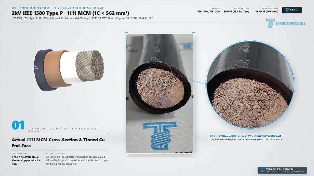
Together, these real inspection segments verify four physical manufacturing details.
- Live 1:1 Optical Macro Check of 2,745 / 24 AWG Tinned Copper (
0:08 to 0:14). First, at0:13above (LIVE FACTORY VIDEO 01 OF 02), a1:1optical macro loupe sits over the saw-cut1111 MCM (562 mm²)end-face. It confirms that all37rope-lay tinned copper sub-bundles fill the 33.7 mm core circle tightly with zero central voids. - Concentric 2.9 mm EPR & 2.4 mm XL-CPE Ring Uniformity (
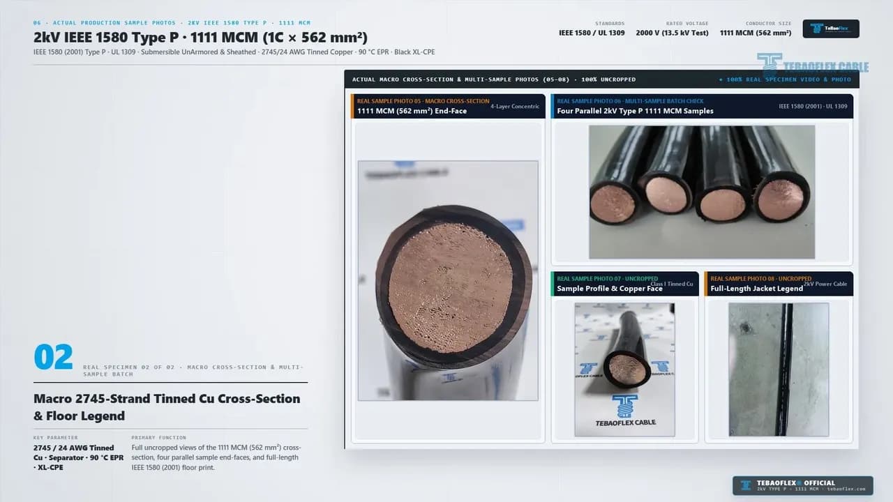
0:08 to 0:14& Photo05). Second, the macro cross-section (Photo 05at1:15) shows a sharp concentric boundary. It separates the inner2.9 mmgrayEPRring, the white helical separator tape, and the outer2.4 mmblackXL-CPEjacket (44.9 mm OD). - Live 1.0x Tracking of White Dot-Matrix Sheath Legend (
0:44 to 0:51). Third, at0:49below (LIVE FACTORY VIDEO 02 OF 02), a horizontal1.0xtracking shot verifies the white dot-matrix legend along the blackXL-CPEsheath. It reads"Submersible 1111 MCM 1C Type P UnArmored & Sheathed 2kV Power Cable to IEEE 1580 (2001)"next to our blue QC tag. - Eight Uncropped Batch Sample Photos (
1:10 to 1:16). Fourth, Section06displaysREAL SPECIMEN 01 OF 02(Photos 01 to 04) andREAL SPECIMEN 02 OF 02(Photos 05 to 08shown below at1:15). They verify standing sample rigidity, four parallel batch end-faces, and full-length floor print legibility.
How Do You Size 1111 MCM Type P Feeders for Offshore Ambient Temperatures?
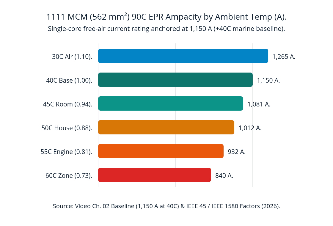
When marine electrical engineers size 2,000 V single-core feeders, the 1,150 A rating at 0:21 represents a 100% baseline factor (kₜ = 1.00) at +40 °C ambient air (IEEE 45, 2026). However, in enclosed offshore VFD rooms or tropical drilling zones (+45 °C to +55 °C), usable ampacity drops to 94% (1,081 A), 88% (1,012 A), and 81% (932 A) per IEEE 1580 (2026).
Consider a 2,000 V offshore derrick top-drive VFD rated at 2,800 A full-load phase current operating inside a +50 °C derrick house (kₜ = 0.88, 1,012 A per core). Running two parallel 1111 MCM cables per phase would only supply 2,024 A. Therefore, the engineer must specify three parallel 1111 MCM (562 mm²) Type P feeders per phase (3 x 1,012 A = 3,036 A) as modeled in Chapter 02 (0:17 to 0:21).
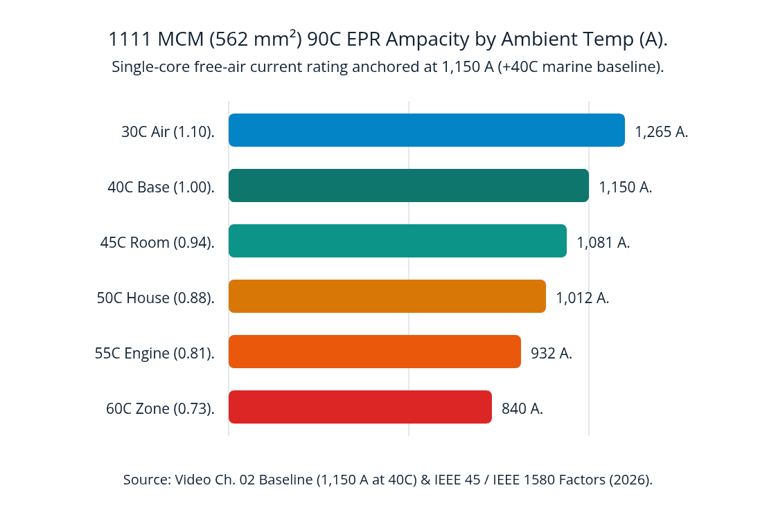
Single-core 1111 MCM (562 mm²) 90C EPR continuous free-air ampacity across offshore ambient temperatures: 30C (1.10) 1,265 A; 40C (1.00) 1,150 A; 45C (0.94) 1,081 A; 50C (0.88) 1,012 A; 55C (0.81) 932 A; 60C (0.73) 840 A. Source: IEEE 45 and IEEE 1580 (2026).
Figure 2: Single-core free-air ampacity derating curve for 1111 MCM (562 mm²) 90 °C EPR Type P cable per IEEE 45 Shipboard Electrical Installations, 2026.
Offshore Ambient Temperature
30 °C Open Deck
- Correction Factor (kₜ):
1.10 - Single-Core Ampacity (1C x 562 mm²): 1,265 A
- 3-Parallel Per Phase Rating: 3,795 A
40 °C Marine Baseline
- Correction Factor (kₜ):
1.00 - Single-Core Ampacity (1C x 562 mm²): 1,150 A (Video Ch. 02 Spec)
- 3-Parallel Per Phase Rating: 3,450 A
45 °C VFD Switchgear Room
- Correction Factor (kₜ):
0.94 - Single-Core Ampacity (1C x 562 mm²): 1,081 A
- 3-Parallel Per Phase Rating: 3,243 A
50 °C Derrick House
- Correction Factor (kₜ):
0.88 - Single-Core Ampacity (1C x 562 mm²): 1,012 A
- 3-Parallel Per Phase Rating: 3,036 A
55 °C Machinery Space
- Correction Factor (kₜ):
0.81 - Single-Core Ampacity (1C x 562 mm²): 932 A
- 3-Parallel Per Phase Rating: 2,796 A
60 °C High-Temp Zone
- Correction Factor (kₜ):
0.73 - Single-Core Ampacity (1C x 562 mm²): 840 A
- 3-Parallel Per Phase Rating: 2,520 A
Top-Drive Service Loop Installation Checklist
- Preserve the
8 x OD(359 mm) Minimum Bend Radius. Ensure hanging loop saddles and gooseneck clamps keep an inner bend radius of at least 359 mm (14.1 in) so the 44.9 mm cable never kinks. - Keep Torsional Twist Within
±180 °/m. Align vertical service-loop clamps neutral to the top-drive travel axis so wind and carriage rotation stay within the verified ±180 °/m torsional rating (0:21and1:07). - Space Parallel Single-Core Feeders on
SS316Ladder Trays. Route parallel1111 MCMsingle-core phase feeders in trefoil groups or with45 mmfree-air spacing to maintain the 1,150 A thermal dissipation profile. - Specify Flared-Entry Class I Compression Lugs. Because
Layer 01(33.7 mmOD) contains 2,745 strands of 24 AWG (ASTM Class I), always use flared-entry marine compression lugs sized for1111 MCMflexible rope-lay tinned copper.
Frequently Asked Questions (FAQ)
What is the exact stranding and metric size of the 1111 MCM Type P conductor?
The 1111 MCM (1,111 kcmil) conductor has a metric cross-section of 562 mm² and a nominal core diameter of 33.7 mm (1.33 in). It is built from 2,745 individual strands of 24 AWG (0.51 mm) annealed tinned copper grouped into 37 rope-lay sub-bundles per ASTM B33 and ASTM B172 Class I.
Why is the 2,000 V Type P cable factory-tested at 13,500 V (13.5 kV) AC for 5 minutes?
Variable-frequency drive (VFD) inverters feeding 2,000 V offshore top-drive and mud-pump motors create steep dV/dt voltage reflections. Testing the 0.115 in (2.9 mm) cross-linked EPR insulation wall at 13,500 V AC for 5 minutes verifies a 6.75x dielectric safety margin against partial discharge per IEEE 1580 and UL 1309.
Does the black XL-CPE outer jacket resist oil-based and ester-based drilling muds?
Yes. The 0.095 in (2.4 mm) heavy-duty black cross-linked chlorinated polyethylene (XL-CPE) jacket is formulated to IEEE 1580 Type P marine standards. It resists swelling and cracking in mineral oil, ester-based synthetic drilling mud, calcium bromide brines, and continuous saltwater submergence while passing IEEE 1202 / CSA FT4 vertical tray flame tests.
What is the minimum bend radius for an offshore derrick top-drive hanging loop?
As shown in Video Chapters 02 (0:21) and 05 (1:04 to 1:10), the minimum dynamic bend radius for the 44.9 mm (1.77 in) cable in a hanging top-drive loop is 8 x OD (359 mm / 14.1 in). It also supports ±180 °/m torsional twist from -40 °C to +90 °C.
Which segments of the 82-second video show the actual physical cable sample?
The physical factory specimen appears in four verified segments. First is the opening cover card (0:00 to 0:03), and second is Chapter 01B (0:08 to 0:14, live 1.0x macro video of the 1111 MCM cut end-face). Third is Chapter 03B (0:44 to 0:51, live 1.0x horizontal tracking video of the white dot-matrix sheath legend and QC tag), and fourth is Chapter 06 (1:10 to 1:16, eight uncropped workshop photos).
Request Factory Test Reports or Offshore VFD Cable Quotations
Planning an offshore drilling rig top-drive service loop refit, mud-pump feeder upgrade, or 2,000 V marine VFD project with TEBAOFLEX® 2kV IEEE 1580 Type P · 1111 MCM (1C x 562 mm²)? Please contact our offshore engineering team or browse our Marine & Reeling Cable Catalog and Engineering Video Library to request 13.5 kV AC factory test reports or custom cut-length quotes (info@tebaoflex.com, +86 185 9591 3361).
Contact TEBAOFLEX on WhatsApp: +86 185 9591 3361