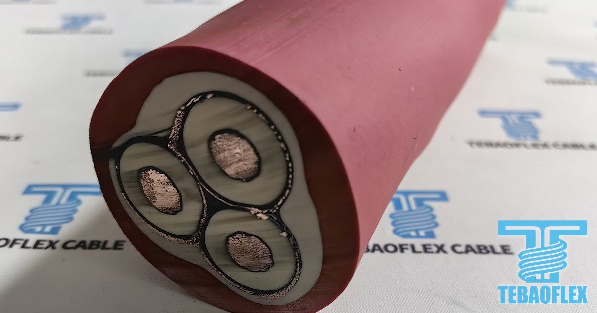
What the video shows
Explore the 2kV Type SHD-GC 3x2 AWG cable through factory footage, six-layer construction diagrams, drill routing, and receiving inspection guidance.
The video illustrates a sample, process, or operating context. Final product construction, suitability, standards, and test acceptance criteria are confirmed against the ordered specification.
TL;DR: This 82-second (1:22) video inspects our TEBAOFLEX® 2kV Type SHD-GC 3x2 AWG + 2x6 AWG + 1x8 AWG shielded cable built to ICEA S-75-381 / NEMA WC 58 (2026) and CSA C22.2 No. 96 (2026). It pairs two uncropped 16:9 live factory videos and nine real sample photos (0:00 to 0:03, 0:08 to 0:14, 0:44 to 0:51, and 1:10 to 1:16) with 3D open-pit blasthole drill and 6-layer cutaway schematics. Inside the 32.5 mm (1.28 in) cord-reinforced black Neoprene / XL-CPE jacket, three 2 AWG (33.6 mm²) rope-lay copper phase cores carry 190 A in 40 °C free air. Each phase uses a 1.78 mm (70 mils) 90 °C EPR wall and a copper braid shield (min. 60% coverage) per ICEA S-75-381 (2026), cabled with 2x6 AWG bare grounds and 1x8 AWG yellow GC pilot for 6 x OD (195 mm) drill reel duty down to -40 °C.
On open-pit rotary blasthole drills (PV-271 class), continuous miners, and mobile crushers, 2,000 V (2 kV) trailing cables face severe mechanical and electrical stress. As the drill rig crawls along a rock bench, its rear drum winds and unwinds the cable across sharp blasted rock while VFD drives inject voltage spikes. Unshielded cables suffer corona damage and lack per-phase fault containment if a rock crushes the jacket. This video page pairs our 82-second factory and 3D walkthrough of the Type SHD-GC Mining Cable (3x2 AWG + 2x6 AWG + 1x8 AWG) with ICEA S-75-381 reel derating tables. You also get a buyer FAT checklist.
What Does the 82-second 2kV SHD-GC 3x2 AWG Video Show?
The 82-second video is split into eight clear segments so mine superintendents and buyers can check both drill reel kinematics and real factory specimens. The table below separates live uncropped factory video and sample photos from 3D engineering schematics.
| Timestamp | Video Chapter | Visual Format | Key Engineering Evidence Verified On-Screen |
|---|---|---|---|
| 0:00 - 0:03 | Opening Specimen & Drill Rig Card | Real Specimen + Quarry Scene | Real 3x2AWG+2x6AWG+1x8AWG cut end-face and vertical legend (TEBAOFLEX® SHD-GC 3C2AWG+2*6AWG+1*8AWG 2kV MSHA) beside a crawler blasthole drill rig. |
| 0:03 - 0:08 | 01 · Cross-Section & Model Reveal | 2D & 3D CAD Geometry | Symmetrical trefoil layout of 3x2 AWG shielded phases with 2x6 AWG bare grounds and 1x8 AWG yellow GC pilot in the three outer valleys. |
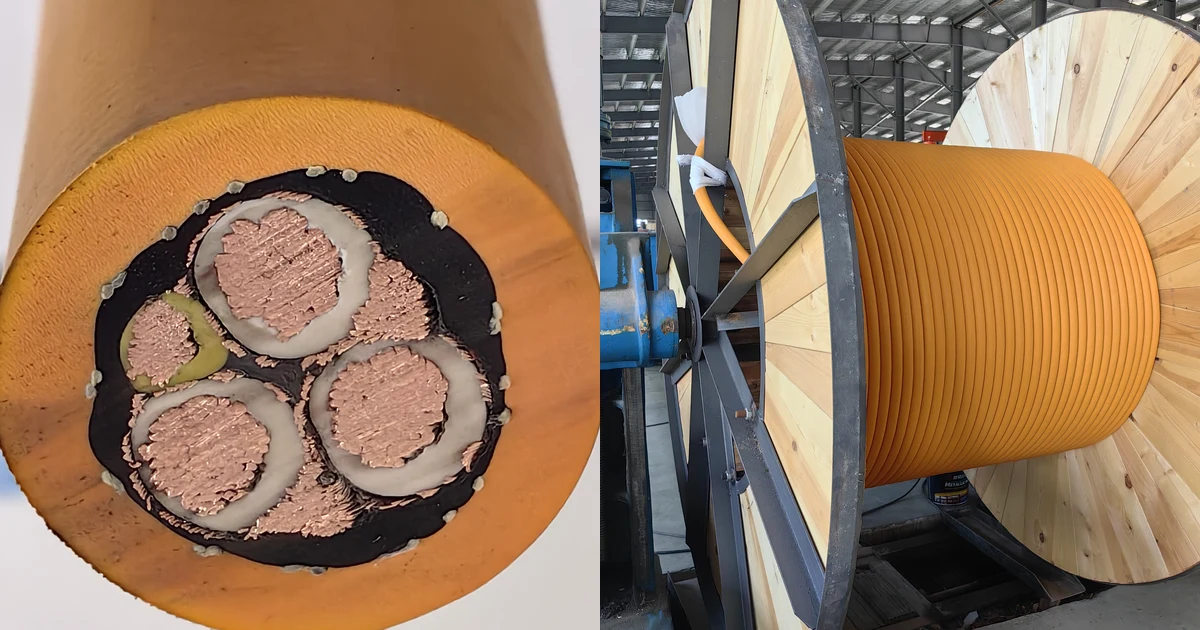
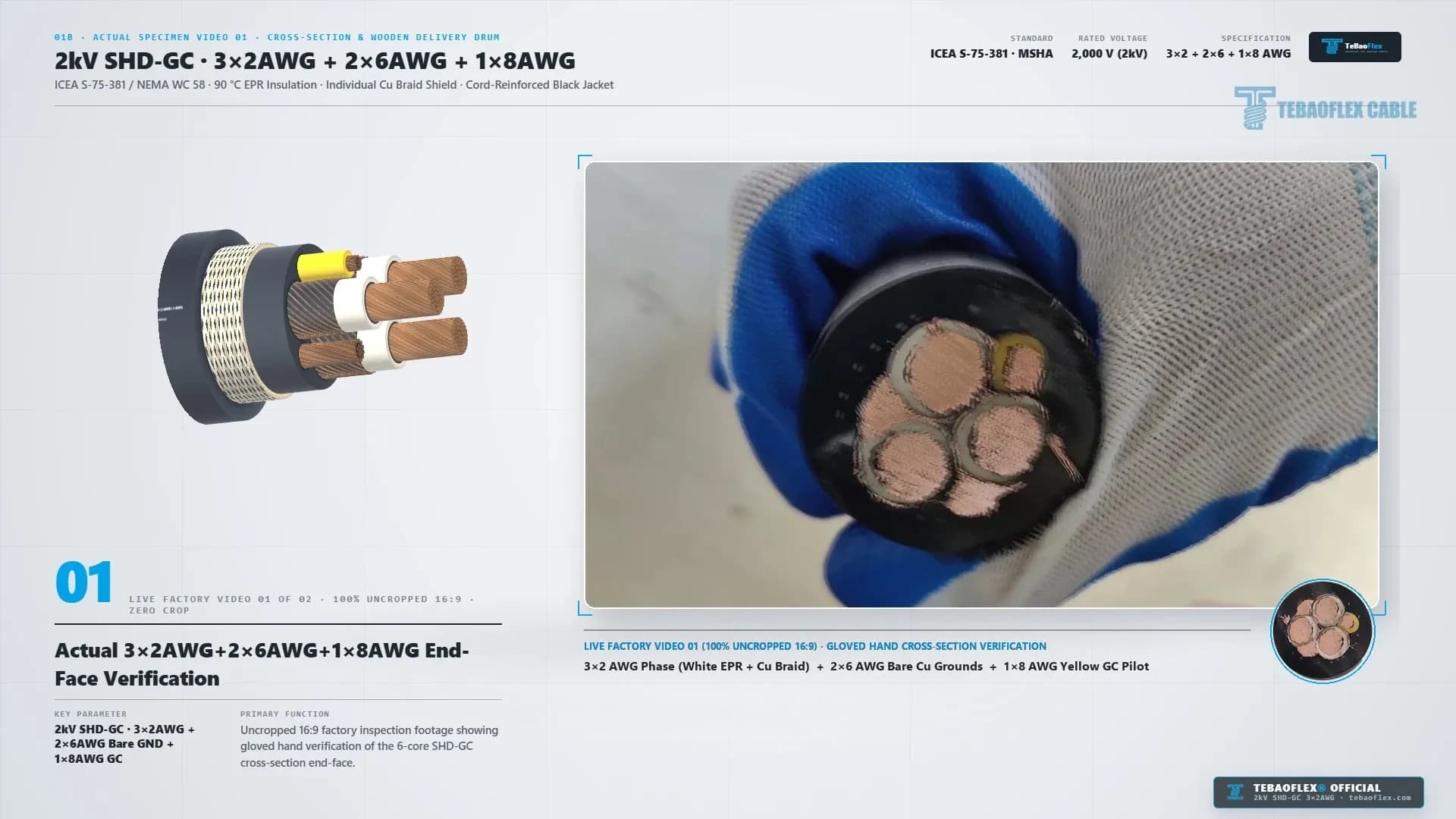
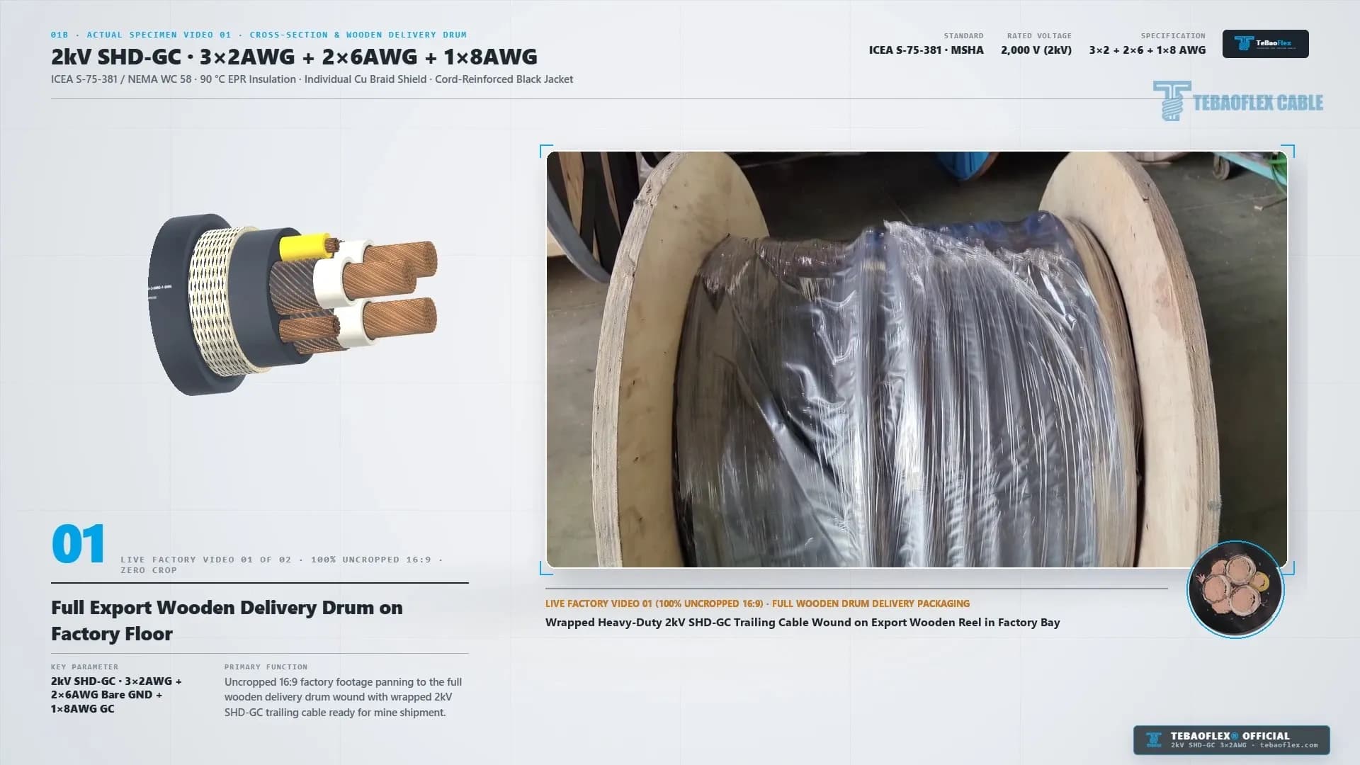
| 0:08 - 0:14 | 01B · Actual Specimen Video 01 | Uncropped 16:9 Live Factory Video | 0:08 to 0:11: Gloved-hand inspection of the real 6-core cut end-face. 0:11 to 0:14: Wrapped 2kV SHD-GC cable wound on an export wooden drum. |
| 0:14 - 0:27 | 02 · Open-Pit Blasthole Drill Scene | 3D Kinematic & X-Ray Schematic | 3-point routing (① 2kV Skid Load Center to ② Tail-Boom Fairlead to ③ Motorized Drill Reel) with 6 x OD (195 mm) bending over a +16.5 m travel run. |
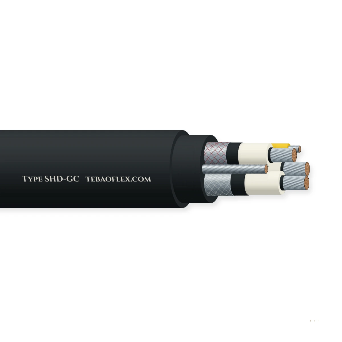
| 0:27 - 0:44 | 03 · 6-Layer Strip-Back (06 to 01) | 3D Stepped Layer Cutaway | Sequential strip-back from Layer 06 (Ø 32.5 mm black jacket) and Layer 05 (cord braid) down to Layer 01 (3x2 AWG rope-lay copper). |
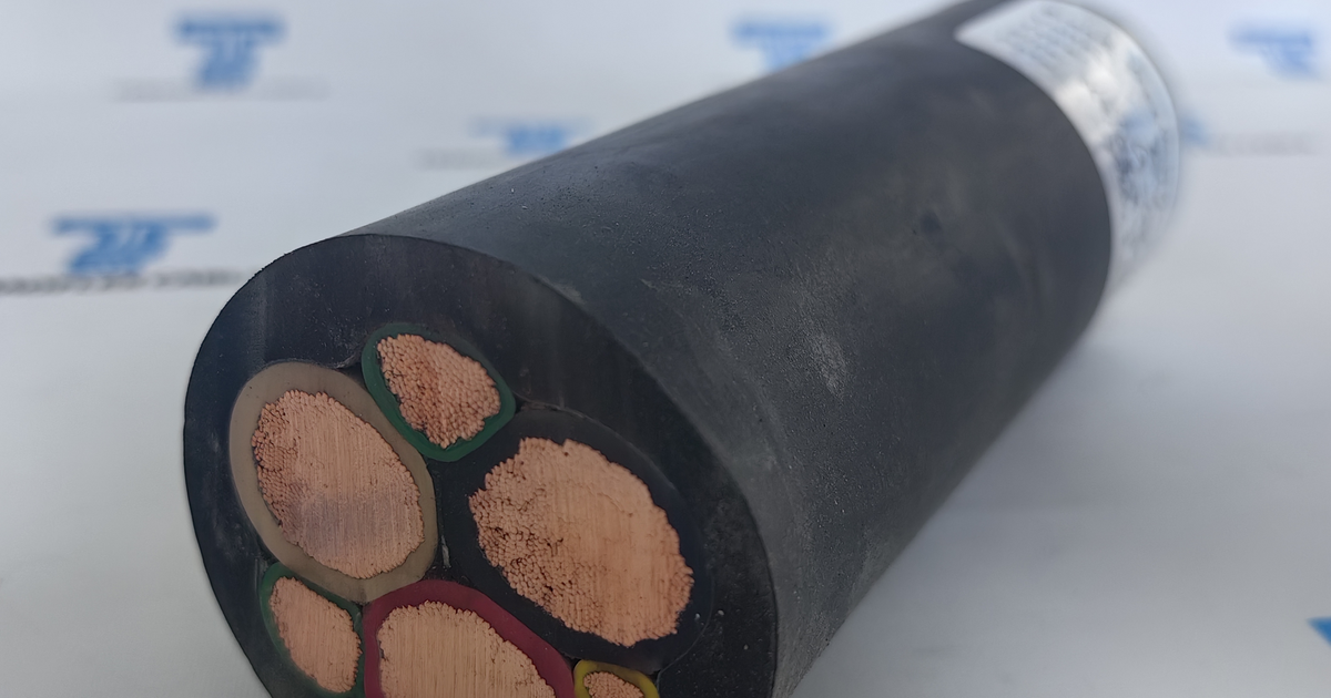
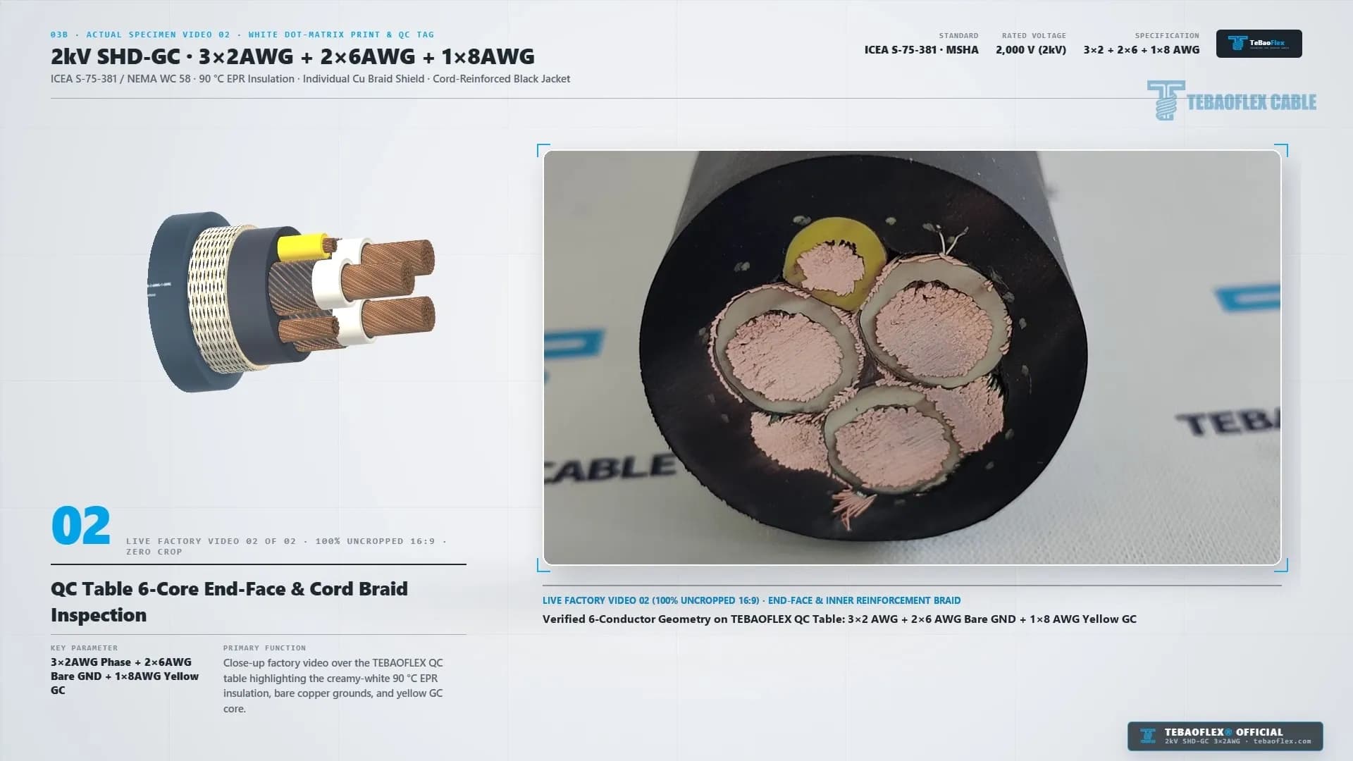
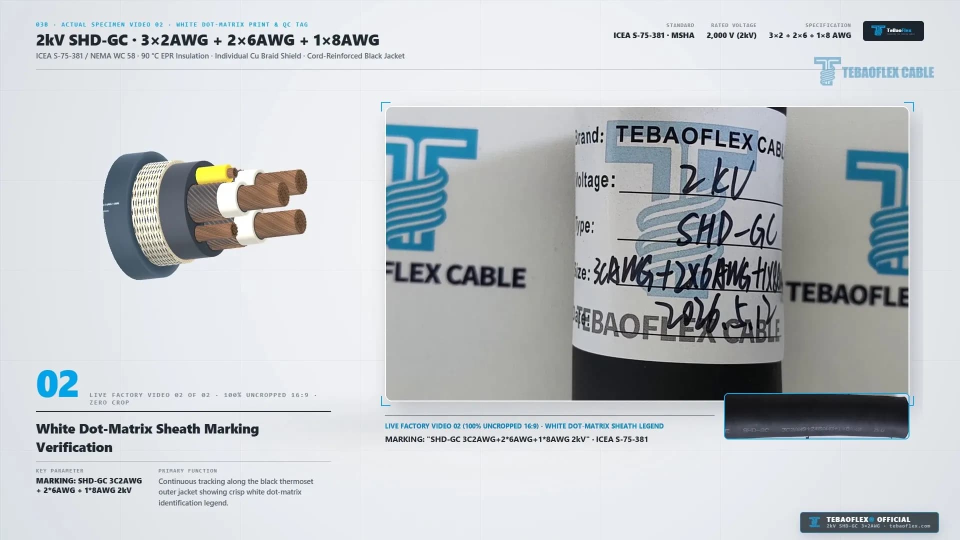
| 0:44 - 0:51 | 03B · Actual Specimen Video 02 | Uncropped 16:9 Live Factory Video | 0:44 to 0:47: QC table end-face check. 0:47 to 0:49: White dot-matrix legend SHD-GC 3C2AWG+2*6AWG+1*8AWG 2kV. 0:49 to 0:51: QC tag (2026.5.12). |
| 0:51 - 1:10 | 04 & 05 · Overview & 6-card Specs | 2D/3D Callout + Spec Matrix | Full 6-layer callout table plus 6-card matrix (2,000 V, 3x2 AWG ~190 A, 2x6 + 1x8 AWG, 90 °C EPR + Cu Braid, 6 x OD, Ø 32.5 mm). |
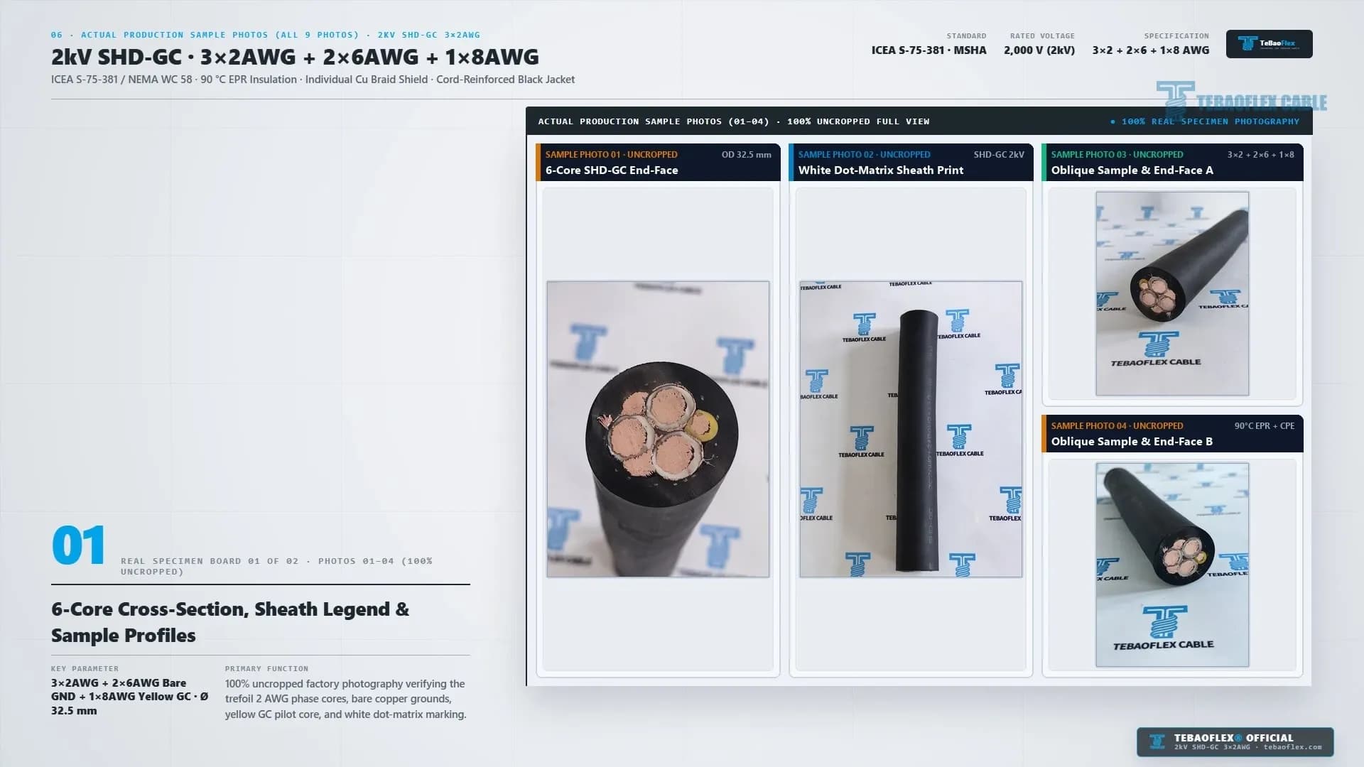
| 1:10 - 1:22 | 06 · 9 Sample Photos & Contact Card | 9 Uncropped Factory Photos | Board 01 (Photos 01 to 04) and Board 02 (Photos 05 to 09) verifying standing pillars, sheath print, and 3-sample batch end-faces. |
A Type SHD-GC cable is an extra-heavy-duty, three-conductor portable mining power cable with individual metallic phase shields (SHD), two uninsulated grounding conductors (G), and one insulated ground-check pilot conductor (GC). It is built to ICEA S-75-381 / NEMA WC 58 and CSA C22.2 No. 96. Even at 2,000 V (2 kV), picking SHD-GC instead of unshielded Type G-GC confines the electric field inside each phase core. That guarantees fast ground-fault tripping if a drill track or rock pierces the jacket.
Technical Specification Summary (2kV SHD-GC 3x2AWG+2x6AWG+1x8AWG)
We compiled the verified parameters from the video inspection cards (0:00 to 1:10) and physical specimen tags alongside the governing North American mining standards for the 3x2 AWG build.
| Parameter | Verified Video Specification | Governing Standard / Benchmark | Practical Mining Field Meaning |
|---|---|---|---|
| Cable Designation | 2kV SHD-GC 3x2AWG+2x6AWG+1x8AWG | ICEA S-75-381 / NEMA WC 58 & CSA C22.2 No. 96 | Extra-heavy-duty shielded portable trailing and reeling cable. |
| Rated Working Voltage | 2,000 V (2 kV) phase-to-phase | ICEA S-75-381 (6.0 kV AC / 5 min test) | Feeds 480 V, 600 V, 995 V, and 1,000 V to 2,000 V mobile mine machinery. |
| Phase Conductors (Layer 01) | 3 x 2 AWG (33.6 mm² per phase) | ASTM B172 / B3 Rope-Lay Stranded Bare Copper | Typically 259 strands (7x37 of 26 AWG), R20 max. 0.532 Ω/km. |
| Conductor Screen & Insulation | Semicon Screen + 90 °C EPR (1.78 mm / 70 mils) | ICEA S-75-381 Table 3-4 (70 mils for 2kV 8 to 4/0 AWG) | Creamy-white ozone-resistant thermoset EPR rated -40 °C to +90 °C (250 °C SC). |
| Phase Metallic Shield (Layer 03) | Individual Flexible Copper Braid Shield | ICEA S-75-381 Sect. 3.15 (min. 60% coverage) | Flexible copper braid over semiconducting insulation screen on each phase. |
| Grounding Conductors (GND) | 2 x 6 AWG (13.3 mm² each) Bare Copper | ICEA S-75-381 Table 3-1 (6 AWG required for 2 AWG phase) | Two uninsulated rope-lay grounds in continuous contact with the three phase shields. |
| Ground-Check Pilot (GC) | 1 x 8 AWG (8.37 mm²) Yellow EPR Core | ICEA S-75-381 Table 3-1 (min. 8 AWG for 2 AWG phase) | High-visibility yellow EPR insulation (45 mils / 1.14 mm) for fail-safe pilot loop. |
| Inner Bedding Jacket (Layer 04) | Integral-Filled Heavy-Duty Black Elastomer | Pressure-extruded thermoset inner jacket | Fills all valley voids to lock the 6-core trefoil geometry under crushing loads. |
| Reinforcing Braid (Layer 05) | High-Tensile Counter-Wound Synthetic Cord | Open-weave nylon / polyester / aramid cord | Vulcanized between inner and outer jackets to stop reel elongation and corkscrewing. |
| Outer Jacket (Layer 06) | Black Neoprene / XL-CPE (MSHA Approved) | 30 CFR Part 7 flame test & heavy-duty tear spec | Resists sharp quarry rock cuts, diesel oil, UV sunlight, and water immersion. |
| Nominal Outer Diameter (OD) | Ø 32.5 mm (1.28 in) | Factory laser diameter & caliper check | Compact round profile (1.95 to 2.15 kg/m / 1,350 lb/1000 ft approx. weight). |
| Min. Dynamic Bend Radius | 6 x OD (195 mm / 7.68 in) | ICEA S-75-381 mobile reeling standard | Fits compact rear-deck blasthole drill reels and tail-boom fairlead rollers. |
| Free-Air Base Ampacity | ~190 A per phase at 40 °C ambient | ICEA S-75-381 (90 °C conductor, 40 °C air) | Supports 150 kW to 500 kW rotary drill compressors and hydraulic packs. |
Engineering Boundary Note (Live Workshop Footage vs. 3D Schematics): Chapters 01B (0:08 to 0:14), 03B (0:44 to 0:51), and 06 (1:10 to 1:16) show uncropped live factory videos and real workshop photos of the manufactured 2kV SHD-GC 3x2AWG+2x6AWG+1x8AWG specimen and export drum. Chapters 01 (0:03 to 0:08), 02 (0:14 to 0:27), 03 (0:27 to 0:44), 04 (0:51 to 1:04), and 05 (1:04 to 1:10) use 3D CAD schematics to illustrate internal layer order and drill bench routing. In the live specimen cuts (0:10, 0:46, and 1:10), the 1.78 mm 90 °C EPR phase insulation looks creamy off-white. Its outer copper braid shield sits tightly around each phase in direct contact with the two 6 AWG bare copper grounds.
Why Specify 2kV Shielded SHD-GC Instead of Type G-GC on Blasthole Drills?
At 2,000 V, ICEA S-75-381 allows both unshielded Type G-GC and shielded Type SHD-GC. However, open-pit blasthole drills, high-wall shovels, and VFD shuttle cars increasingly prefer 2kV Type SHD-GC. That preference comes from the 6-layer shielded and cord-reinforced build shown in Chapter 03 (0:27 to 0:44).
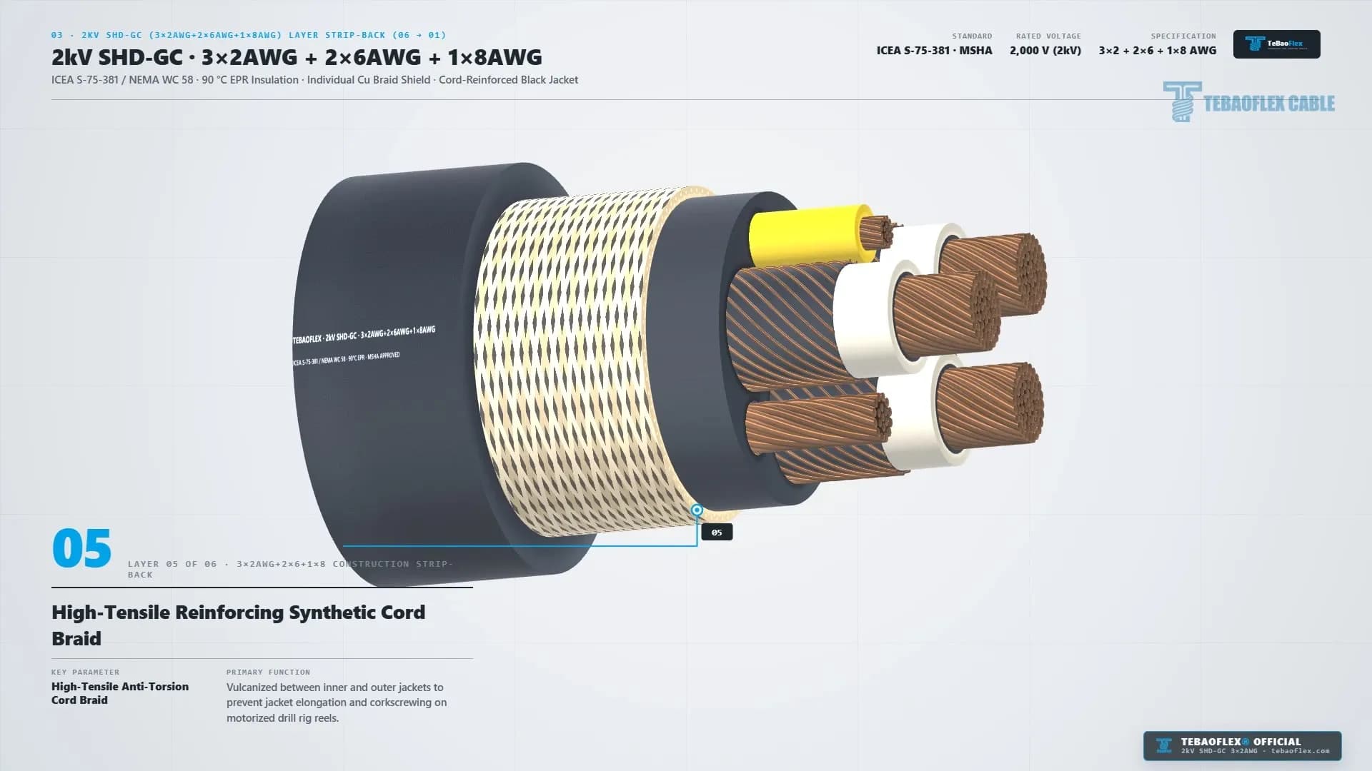
An integral-filled cord-reinforced double jacket is a two-stage thermoset sheath system in which a pressure-extruded inner jacket (Layer 04) fills the core valleys and an open counter-wound cord braid (Layer 05) locks into an extra-heavy-duty outer jacket (Layer 06). Vulcanizing the inner and outer elastomer walls through the braid openings prevents jacket slippage and corkscrewing on high-torque drill reels.
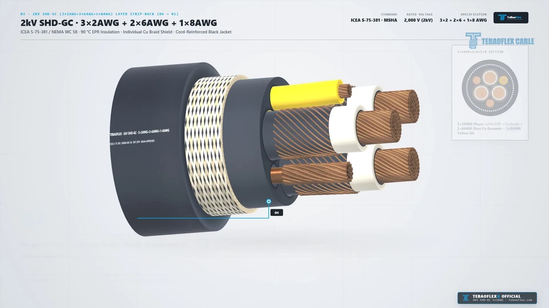
Working from the center conductor outward (Layer 01 to Layer 06), each structural layer solves a specific open-pit drilling hazard.
- Layer 01: 3 x 2 AWG (33.6 mm²) Rope-Lay Stranded Bare Copper Phase Cores (0:41 to 0:44). We strand annealed bare copper wires per ASTM B172 / B3 in a flexible rope-lay pattern (for example, 7 x 37 wires of 26 AWG). Rope-lay stranding survives constant reverse bending over the drill tail-boom fairlead roller (min. 6 x OD = 195 mm) while carrying ~190 A per phase.
- Layer 02: Semiconductive Conductor Screen & 1.78 mm (70 mils) 90 °C EPR Insulation (0:38 to 0:41). An extruded semiconducting layer smooths strand ridges beneath the 1.78 mm (70 mils) thermoset ethylene propylene rubber (EPR) dielectric wall. Rated from -40 °C to +90 °C continuous duty and 250 °C short-circuit temperature, the creamy-white EPR wall resists ozone, moisture, and VFD voltage spikes.
- Layer 03: Individual Phase Copper Braid Shields + 2 x 6 AWG Bare GND + 1 x 8 AWG Yellow GC (0:35 to 0:38). Each 2 AWG phase is wrapped in a semiconducting screen and a flexible copper braid shield (min. 60% optical coverage per ICEA S-75-381 (2026)). In the three outer valleys sit two uninsulated 6 AWG (13.3 mm²) bare copper grounds and one bright yellow 8 AWG (8.37 mm²) EPR-insulated Ground-Check (GC) core. Because the bare 6 AWG grounds touch the copper braid shields along the full cable length, any rock puncture hits a grounded shield first.
- Layer 04: Integral-Filled Heavy-Duty Black Elastomeric Inner Jacket (0:32 to 0:35). We extrude this black inner jacket under high pressure to fill every valley between the three shielded phases, two bare grounds, and yellow GC core. As seen in the 0:10 and 0:46 live cuts, this solid elastomer bed stops core migration and blocks water ingress.
- Layer 05: High-Tensile Counter-Wound Reinforcing Synthetic Cord Braid (0:29 to 0:32). We vulcanize this open cord braid directly between the black inner and outer jackets. In the 0:10 and 0:46 live end-face videos, it appears as a distinct white fiber ring inside the black sheath wall that absorbs pulling tension and reel torque.
- Layer 06: Extra-Heavy-Duty Black Neoprene / XL-CPE Outer Jacket (0:27 to 0:29). This outer sheath passes MSHA 30 CFR Part 7 flame-resistance testing while keeping a compact Ø 32.5 mm (1.28 in) outer diameter. It resists sharp granite, iron-ore, and copper-porphyry bench rock.
For a full comparison of 2 kV to 25 kV portable mining standards, read our guide on ICEA S-75-381 Mining Cables: Type W, Type G-GC, and Type SHD-GC Explained.
How Does 3-point Blasthole Drill Bench Routing Work in Open-Pit Mines?
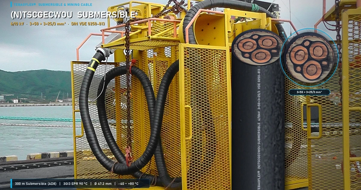
In Chapter 02 (0:14 to 0:27), the video maps the field routing of the 2kV SHD-GC 3x2AWG+2x6AWG+1x8AWG trailing cable on an open-pit rock bench (Mine Bench Level -120m alongside 300T haul trucks). Instead of sitting static in a tray, the cable runs through three active zones shown at 0:17 to 0:24.
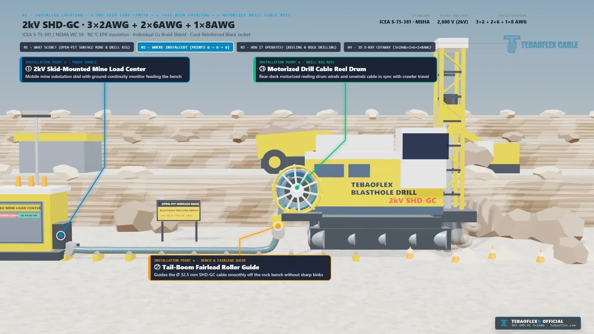
- Point ①: 2kV Skid-Mounted Mine Load Center (0:17 to 0:21). The cable starts at a portable bench substation skid fitted with a vacuum breaker, a neutral grounding resistor (100 V max. touch voltage), and a Ground-Check (GC) pilot monitor. The yellow 8 AWG GC core forms a closed loop with the two 6 AWG bare grounds to trip the 2,000 V breaker if the ground path opens.
- Point ②: Tail-Boom Fairlead Roller Guide (0:17 to 0:24). As the crawler drill advances from hole to hole (Travel: +16.5 m per pass shown at 0:22), the four-roller tail-boom fairlead lifts the Ø 32.5 mm cable off the blasted rock bench. Keeping the fairlead roller radius at or above 6 x OD (195 mm / 7.68 in) prevents kinking and braid wire fatigue when the rig turns 90° between blasthole rows.
- Point ③: Motorized Drill Cable Reel Drum (0:17 to 0:27). The rear-deck hydraulic torque reel pays out cable as the crawler moves forward and winds it back in tight layers as the rig reverses. During active rotary drilling, 1 to 4 layers of cable stay coiled on the drum barrel, trapping heat and requiring ampacity derating.
How Do You Size 2kV SHD-GC 3x2 AWG Ampacity for Multi-Layer Drill Reels?
Video Chapter 05 (1:04 to 1:10) lists the standard ICEA S-75-381 free-air ampacity of ~190 A per phase. That 190 A table rating applies to a 3-conductor 2 AWG shielded SHD-GC cable at 90 °C conductor temperature in 40 °C air. However, when a blasthole drill or continuous miner runs with multiple cable layers coiled on its rear reel, heat dissipation drops sharply.
Under ICEA S-75-381 / NEMA WC 58 (2026) Part 8, engineers must apply both the ambient temperature factor (kₜ) and the reel layer derating factor (kᵣ). For coiled reels, use k_R = 0.85 for 1 layer (85%) and k_R = 0.65 for 2 layers (65%) per ICEA S-75-381 (2026). For deeper wraps, use k_R = 0.45 for 3 layers (45%) and k_R = 0.35 for 4 layers (35%) per ICEA S-75-381 (2026).
ICEA S-75-381 Reel Layer & Ambient Ampacity Derating Table (2kV SHD-GC 3x2 AWG)
Ambient factors and free-air current
| Ambient Bench Temp (Tₐ) | Thermal Factor (kₜ) | Free Air / Single Bench Run (k_R = 1.00) |
|---|---|---|
| 30 °C (86 °F) | 1.10 | 209.0 A |
| 40 °C (104 °F) | 1.00 | 190.0 A |
| 45 °C (113 °F) | 0.95 | 180.5 A |
| 50 °C (122 °F) | 0.89 | 169.1 A |
Current by number of reel layers
| Ambient Bench Temp (Tₐ) | 1 Layer on Drill Reel (k_R = 0.85) | 2 Layers on Drill Reel (k_R = 0.65) | 3 Layers on Drill Reel (k_R = 0.45) | 4 Layers on Drill Reel (k_R = 0.35) |
|---|---|---|---|---|
| 30 °C (86 °F) | 177.7 A | 135.9 A | 94.1 A | 73.2 A |
| 40 °C (104 °F) | 161.5 A | 123.5 A | 85.5 A | 66.5 A |
| 45 °C (113 °F) | 153.4 A | 117.3 A | 81.2 A | 63.2 A |
| 50 °C (122 °F) | 143.7 A | 109.9 A | 76.1 A | 59.2 A |
Voltage drop over a 150 m run
| Ambient Bench Temp (Tₐ) | 3-Phase Voltage Drop per 150 m (500 ft) at 123.5 A (cos φ = 0.85) |
|---|---|
| 30 °C (86 °F) | 20.4 V (1.02% at 2,000 V / 4.25% at 480 V). |
| 40 °C (104 °F) | 20.4 V (1.02% at 2,000 V / 4.25% at 480 V). |
| 45 °C (113 °F) | 19.4 V (0.97% at 2,000 V / 4.04% at 480 V). |
| 50 °C (122 °F) | 18.2 V (0.91% at 2,000 V). |
Wait for thermal equilibrium before full-load drilling. Ground-check (GC) pilot loop monitoring is a fail-safe circuit required by MSHA 30 CFR Part 75 (2026) that sends a pilot signal through the 8 AWG GC core and returns it via the 6 AWG bare grounds. If the ground path breaks, it trips the substation breaker within milliseconds.
We calculated this voltage-drop methodology using 2 AWG (33.6 mm²) rope-lay copper DC resistance R₂₀ = 0.532 Ω/km, operating 90 °C AC resistance R₉₀ = 0.678 Ω/km, and 2kV SHD-GC reactance X_L = 0.102 Ω/km. At 123.5 A (the 2-layer reel limit at 40 °C), a 150 m (500 ft) trailing run drops 20.4 V. For example, on a 2,000 V drill bus, that equals just 1.02% voltage drop (428 kVA load), whereas on a 480 V drill rig it equals 4.25% (102 kVA load). For 8 kV to 25 kV shovel sizing, see our Type SHD-GC 8kV, 15kV & 25kV Ampacity & Voltage Drop Guide.
How Does 2kV Type SHD-GC Compare with Type G-GC, Type W, and MP-GC?
To help mine electrical engineers pick the right ICEA S-75-381 cable family for each machine, the table below compares 2kV Type SHD-GC 3x2 AWG against related portable and feeder cables.
| Cable Type | Rated Voltage | Phase Shielding | Ground & GC Pilot Cores | Reeling & Trailing Duty | Primary Mining Equipment Application |
|---|---|---|---|---|---|
| 2kV Type SHD-GC 3x2 AWG (This Video) | 2,000 V (2 kV) | Individual Copper Braid Shield (min. 60%) + Semicon Screen | 2 x 6 AWG Bare GND + 1 x 8 AWG Yellow GC | Extreme Mobile Reeling & Trailing (6 x OD = 195 mm, Cord-Reinforced) | Rotary blasthole drills (995V / 2kV), VFD continuous miners, high-wall drills, and mobile crushers. |
| 2kV Type G-GC | 2,000 V (2 kV) | Unshielded Phases (90 °C EPR only) | 2 x 6 AWG Insulated/Bare GND + 1 x 8 AWG GC | Heavy-Duty Trailing & Moderate Reeling | Standard 480 V and 600 V AC loaders, shuttle cars, portable pumps, and stage loaders. |
| 2kV Type W | 2,000 V (2 kV) | Unshielded Phases | No dedicated interstitial GC pilot (2, 3, 4, or 5 cores) | General Heavy-Duty Portable & Reel Duty | DC shuttle cars, magnet cranes, portable generators, and industrial shore-power reels. |
| 5kV to 25kV Type SHD-GC | 5 kV / 8 kV / 15 kV / 25 kV | Extruded Semicon + Tinned Copper Braid Shield (60% to 85%) | 2 x GND + 1 x Insulated GC | Extra-Heavy-Duty Shovel & Dragline Trailing (6 x OD to 8 x OD) | Electric rope shovels (4.16 kV to 13.8 kV), walking draglines, and bucket-wheel excavators. |
| Type MP-GC Feeder | 5 kV to 25 kV | Helical Copper Tape Shield (100% coverage) | 2 x Bare GND + 1 x Insulated GC | Fixed or Semi-Permanent Borehole / Tunnel Feeder (12 x OD bend) | Substation-to-skid mine power feeders, shaft drops, and permanent tunnel distribution (NEMA WC 58). |
For a real field deployment of 2,000 V Type SHD-GC cables in South American hard-rock copper mining, read our Peru 2000V Type SHD-GC Mining Cable Case Study.
What Do the 2 Live Factory Videos and 9 Sample Photos Verify for QA?
A key strength of this 82-second video is that it includes three real-specimen inspection blocks: 01B (0:08 to 0:14), 03B (0:44 to 0:51), and 06 (1:10 to 1:16). When your site receiving team inspects a wooden drum of TEBAOFLEX® 2kV SHD-GC 3x2AWG+2x6AWG+1x8AWG, they can check five physical quality details against these uncropped workshop frames.
Buyer Receiving & Pre-Shipment FAT Inspection Checklist
- Verify the White Dot-Matrix Sheath Legend (0:01, 0:47 to 0:49, and 1:10 to 1:13). Inspect the matte black thermoset outer jacket (Ø 32.5 mm). As tracked in Live Video 03B (0:48) and Sample Photo 02 (1:10), confirm the crisp white dot-matrix legend reading "SHD-GC 3C2AWG+2*6AWG+1*8AWG 2kV". Also check the full order legend "TEBAOFLEX® SHD-GC 3C2AWG+2*6AWG+1*8AWG 2kV MSHA".
- Audit the Physical Factory QC Sample Tag (0:49 to 0:51). Every factory test length and export drum carries a signed QC identification label matching the specimen tag filmed at 0:50. It records Brand: TEBAOFLEX CABLE, Voltage: 2kV, Type: SHD-GC, Size: 3x2AWG+2x6AWG+1x8AWG, and Date: 2026.5.12.
- Check the 6-Core Trefoil End-Face & 1.78 mm Creamy-White EPR Wall (0:08 to 0:11 & 0:44 to 0:47). Compare a flush cut against the gloved-hand check (0:10) and QC table macro view (0:46). Verify that the three 2 AWG (33.6 mm²) rope-lay copper cores have uniform 1.78 mm (70 mils) creamy-white 90 °C EPR walls and individual copper braid shields. Also check that the two 6 AWG bare copper grounds and one yellow 8 AWG GC core sit tightly inside the three outer valleys.
- Confirm the Vulcanized Anti-Torsion Reinforcing Cord Braid (0:10, 0:30, and 0:46). Look at the outer black jacket wall on the cut end-face (0:10 and 0:46). You can see the ring of white high-tensile synthetic cords embedded between the integral-filled black inner jacket and the black Neoprene / XL-CPE outer sheath. That confirms two-pass reinforced extrusion.
- Inspect Export Drum Packaging (0:11 to 0:14) & Routine FAT Test Reports. As shown in Live Video 01B (0:12), export drums are traverse-wound and protective-wrapped on flanged wooden reels. Before dispatch, check the batch Factory Acceptance Test (FAT) report covering 20 °C conductor DC resistance (max. 0.532 Ω/km for 2 AWG per ICEA S-75-381), 6.0 kV AC 5-minute dielectric testing, and GC continuity.
Frequently Asked Questions About 2kV SHD-GC 3x2 AWG Cables
Why do 2,000 V blasthole drills use Type SHD-GC instead of unshielded Type G-GC?
Although both cables are rated for 2,000 V under ICEA S-75-381, Type SHD-GC adds an extruded semiconductive screen and a flexible copper braid shield (min. 60% coverage) per ICEA S-75-381 (2026) over each 2 AWG phase core. On rotary blasthole drills and VFD mining machines, per-phase shielding blocks switching noise and forces any rock-crush fault straight to the 2x6 AWG ground path.
Why are the two 6 AWG grounding conductors bare while the 8 AWG GC core is yellow-insulated?
In Type SHD-GC cables, the two 6 AWG (13.3 mm²) grounding conductors (GND) are left uninsulated so they stay in continuous parallel contact with the three phase copper braid shields. By contrast, the 8 AWG (8.37 mm²) Ground-Check (GC) pilot core has a 1.14 mm (45 mils) bright yellow EPR wall. That insulation lets the substation relay send an isolated monitoring loop out through the GC wire and back through the bare grounds.
What is the minimum bending radius for the Ø 32.5 mm 2kV SHD-GC 3x2 AWG cable on a drill reel?
As verified in Video Chapters 02 (0:22) and 05 (1:05), the minimum dynamic bending radius for this Ø 32.5 mm (1.28 in) cable is 6 x OD (195 mm / 7.68 in). Its rope-lay 3x2 AWG copper stranding and counter-wound cord braid (Layer 05) allow smooth winding over compact drill reels and fairlead rollers without corkscrewing.
How much current can 2kV SHD-GC 3x2 AWG carry when wound on a motorized drill reel?
In 40 °C free air (single cable resting on the quarry bench), 3x2 AWG SHD-GC carries 190 A per phase. When coiled on a motorized drill reel at 40 °C, apply the ICEA S-75-381 layer derating factors. The cable carries 161.5 A for 1 layer (0.85), 123.5 A for 2 layers (0.65), 85.5 A for 3 layers (0.45), and 66.5 A for 4 layers (0.35).
Which segments of the 82-second video show the actual physical cable sample?
The physical manufactured cable appears in four verified segments. You can inspect it on the opening cover card (0:00 to 0:03) and in Chapter 01B (0:08 to 0:14, gloved-hand 6-core end-face check and wrapped wooden export drum). It also appears in Chapter 03B (0:44 to 0:51, QC table end-face, "SHD-GC 3C2AWG+2*6AWG+1*8AWG 2kV" white dot-matrix legend, and 2026.5.12 QC tag) and Chapter 06 (1:10 to 1:16, nine uncropped workshop photos).
Request a Quote or Sample for 2kV Type SHD-GC Mining Cables
Whether you are replacing trailing cables on open-pit drills (such as PV-271 rigs) or buying MSHA and ICEA S-75-381 Type SHD-GC cables (2 kV to 25 kV), our team can help. We supply cut sample specimens, datasheets, and pre-shipment FAT reports. Browse our Mining Trailing Cable Portfolio or contact TEBAOFLEX engineering for a fast quote.
WhatsApp: +86 185 9591 3361.