

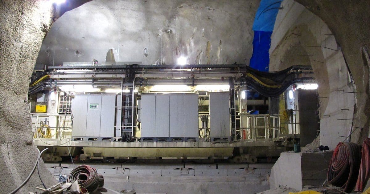
A tunnel boring machine (TBM) cable is the moving medium-voltage (MV) cable between the tunnel's fixed supply network and the machine. On a reeling TBM, the same cable often also carries the protective earth, control and monitoring circuits. Our (N)TSCGECWÖU TBM cable page describes this kind of design, and related cables for mines and tunnels sit in our mining and tunnelling range.
DGUV Information 203-098, guidance from the German Social Accident Insurance umbrella body (Deutsche Gesetzliche Unfallversicherung, DGUV), covers electrical equipment in tunnelling for Germany and Austria. It says tunnel boring and shield machines mostly run from high voltage (HV), for example 6 to 20 kV, and have their own transformer stations. Power demand is usually expected to fall between 2 and 6 MW.
Key Takeaways
- Most tunnel boring and shield machines run from HV, for example 6 to 20 kV, DGUV guidance says. They have their own transformer stations and usually draw 2 to 6 MW.
- Three feed methods appear in the DGUV guide: a reel on the machine, a cable store or drum, or dragging. Dragging can cause large tensile forces, so the guide recommends a tensile-resistant armoured cable and, where no cable drum is fitted, a tension limiter.
- HV junction boxes may be opened only when dead, DGUV states. A lid switch can, for example, open the monitoring conductor and trip the upstream HV switch.
- For portable or mobile HV equipment in US tunnel construction, Occupational Safety and Health Administration (OSHA) rules require the equipment grounding conductor inside the metal raceway or multiconductor cable jacket. Bonding to pipes and rails follows at the portal and at intervals not exceeding 1,000 feet (about 305 m). Both appear in Title 29 of the Code of Federal Regulations (CFR), section 1926.408(a)(4).
- Fire controls for TBMs in a draft code of practice from SafeWork New South Wales (NSW) include fire resistant power cables for the HV supply.
How a TBM Gets Its Power
The TBM power cable links the tunnel's fixed HV network to a transformer on or behind the machine. The August 2026 edition of the DGUV guide says that, given the power demand of current machines or long drives, only an HV supply is possible. The HV transformers are either integrated in the machine or carried behind it as mobile units. Tunnel sites often use HV installations, currently up to 20 kV; in this guidance, HV means above 1 kV under German standard VDE 0101, which includes these MV cables.
Electrical installations on tunnel sites must meet substantially higher requirements than those on surface sites, the guide adds. Only authorised, instructed electrically skilled persons with switching authority may operate or work on HV installations.
Mobile transformer stations may use only cast-resin, dry-type or silicone-fluid transformers, the guide states. If a transformer is damaged, a fast-acting protective device must disconnect all poles. For US tunnel construction, 29 CFR 1926.800(s)(3) bars oil-filled transformers underground unless they sit in a fire-resistant enclosure, vented to the outside and surrounded by a dike.
On Melbourne's North East Link, the network operator's project page says a new zone substation will provide a dedicated 22 kV supply for building and running twin three-lane tunnels. It will initially power the project's two TBMs. That figure is the site supply voltage, not a TBM cable rating.
The NSW draft code notes that larger-diameter TBMs bring higher power requirements. It also calls a reliable main supply to the works essential.
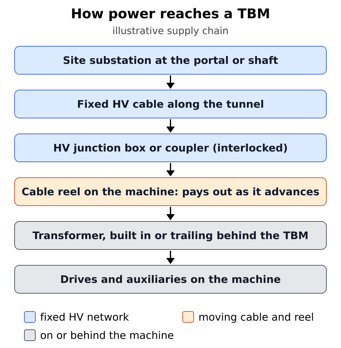
Illustrative supply chain from the site substation to a TBM. DGUV guidance says tunnel boring and shield machines mostly run from HV, for example 6 to 20 kV, with transformers built into the machine or carried behind it. It describes a drum on the machine that pays out cable as the machine moves forward, and HV junction boxes that may be opened only when dead.
Illustrative chain of six steps. A site substation at the portal or shaft feeds a fixed HV cable along the tunnel. An interlocked HV junction box or coupler links it to a cable reel on the machine, which pays out cable as the machine advances. A transformer built into the machine or trailing behind it supplies the drives and auxiliaries.
Three Ways to Feed a TBM Cable
The DGUV guide describes three ways to feed the cable. It presents them as means of reducing tensile forces and mechanical hazards.
- Reel on the machine. The drum can be coupled to the travel drive, paying out as the machine moves forward and winding in as it moves back. No significant tensile forces arise, so extra tensile armouring can be omitted, but the cable must suit repeated reeling.
- Cable store or drum. The cable is stored in a cable store or on a drum and taken off twist-free as the machine advances. Only low tensile stress results.
- Laid out and dragged. The whole length is laid out in front of or inside the structure and dragged by the machine. Large tensile forces are possible, and vehicles and plant can damage the cable, so a tensile-resistant armoured cable is recommended.
Where the machine has no design measure such as a cable drum, the cable's machine connection should have a tension limiter. The limiter stops the advance automatically, with or without a warning, once the permitted tension is exceeded.
US Mine Safety and Health Administration (MSHA) rules in 30 CFR Part 57 cover underground metal and nonmetal mines. Section 57.12014 bars moving cables energised above 150 V phase-to-ground with equipment, unless insulated sleds or slings are used. The rule does not prohibit equipment from pulling or dragging the cable that powers it, when the cable is mechanically attached and insulated from it.
Our reeling cable range covers designs for the first method, and our bucket-wheel excavator reeling cable guide explains reel types and layer currents. For MV cables that are dragged rather than reeled, see our shovel and dragline trailing cable guide.
Inside a TBM Reeling Cable
A TBM reeling cable can combine three insulated MV power cores, each with its own protective-earth screen, plus control cores and an overall monitoring conductor under inner and outer sheaths. Our (N)TSCGECWÖU datasheet lists this build, from the conductor outwards:
- Phase conductors: Class 5 finely stranded tinned copper.
- Insulation: 3GI3 ethylene propylene rubber (EPR) with inner and outer semiconductive rubber layers for field control.
- Protective earth: a tinned copper and textile braid, concentric over each power core.
- Control cores: three tinned copper cores with a semiconductive layer, laid in the outer interstices.
- Inner sheath: GM1b EPR.
- Monitoring conductor: an overall concentric copper-wire layer.
- Outer sheath: red 5GM5 elastomer.
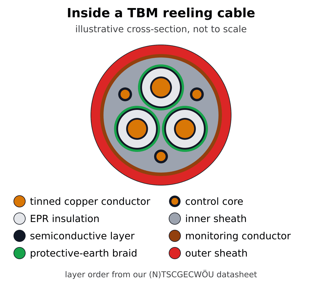
Illustrative cross-section of a TBM reeling cable, not to scale. Each of the three power cores has semiconductive layers around its insulation and its own protective-earth braid. Three control cores sit in the outer gaps, and an overall copper-wire monitoring conductor lies between the inner and outer sheaths. Layer order follows our (N)TSCGECWÖU datasheet.
Illustrative cross-section, not to scale. Three power cores, each with a tinned copper conductor, a semiconductive layer, EPR insulation, a second semiconductive layer and a protective-earth braid. Three smaller control cores sit in the outer gaps between the power cores. An inner sheath fills the gaps, and an overall copper-wire monitoring conductor lies over it, under a red outer sheath.
One configuration row reads 3x95 + 3x50/3E + 3x2.5ST + 6UELKON. That means three 95 mm² phase cores, then the entry for the concentric earth braids over each core. Next come three 2.5 mm² control cores, marked ST, and an overall concentric monitoring conductor, written ÜL KON or UELKON. Our shielded cable guide explains what the semiconductive layers and screens do.
DGUV guidance describes cable designs with a concentric or individually concentric protective conductor. A separate monitoring conductor is needed to check it for a break. Cables with two monitoring screens, one each for the protective and monitoring conductors, are mostly used. Where demands are higher, for example with blasting or explosive atmospheres, they must be used.
The guide's appendix of cables used in tunnelling lists the NTSCGECWÖU type as a reelable supply cable for TBMs with monitoring and control cores. That entry, for rated voltages up to 20 kV, describes a cable type rather than approving any product.
Earthing, Monitoring and Interlocks
The monitoring conductor lets protection trip the supply when the earth path breaks or a fault appears. DGUV guidance says underground HV networks on tunnel sites are, as a rule, to be built with an isolated neutral, citing European standard (EN) 50628.
The faults to consider are a monitoring-to-protective conductor short, a break in the protective-conductor monitoring circuit, a single complete earth fault and a phase-to-monitoring short. Protective devices must ensure that the faulty part cannot be switched back on after tripping.
HV junction boxes may be opened only when dead, the guide says. For example, a safety switch on the lid can open the monitoring conductor and trip the upstream HV switch. HV plugs and sockets may separate only when dead, for example via leading pilot contacts that open the monitoring circuit and trip the upstream switch.
Cable connections to machines, equipment and transformers must be strain-relieved. The protective conductor must get extra length, so excessive tension breaks it last. DGUV also calls for a bonding conductor run apart from the cables, at least 50 mm² copper or equivalent. It links to pipes, rails or other metal at most every 100 m.
29 CFR 1926.408(a) covers US construction systems over 600 V, nominal, and puts the power cable terminals on mobile machines in a metallic enclosure. Its tunnel paragraph lets multiconductor portable cable supply mobile equipment, with the equipment grounding conductor inside the jacket and a disconnecting means at each transformer or motor location. Cable sheaths and other metal parts must be grounded and bonded to pipes and rails at the portal and at intervals not exceeding 1,000 feet.
In US underground metal and nonmetal mines, 30 CFR 57.12017 requires de-energising power circuits before work, unless hot-line tools are used. Warning signs are required, and switches are locked out or otherwise secured. Our mine power feeder cable guide covers fixed MV feeders and neutral earthing.
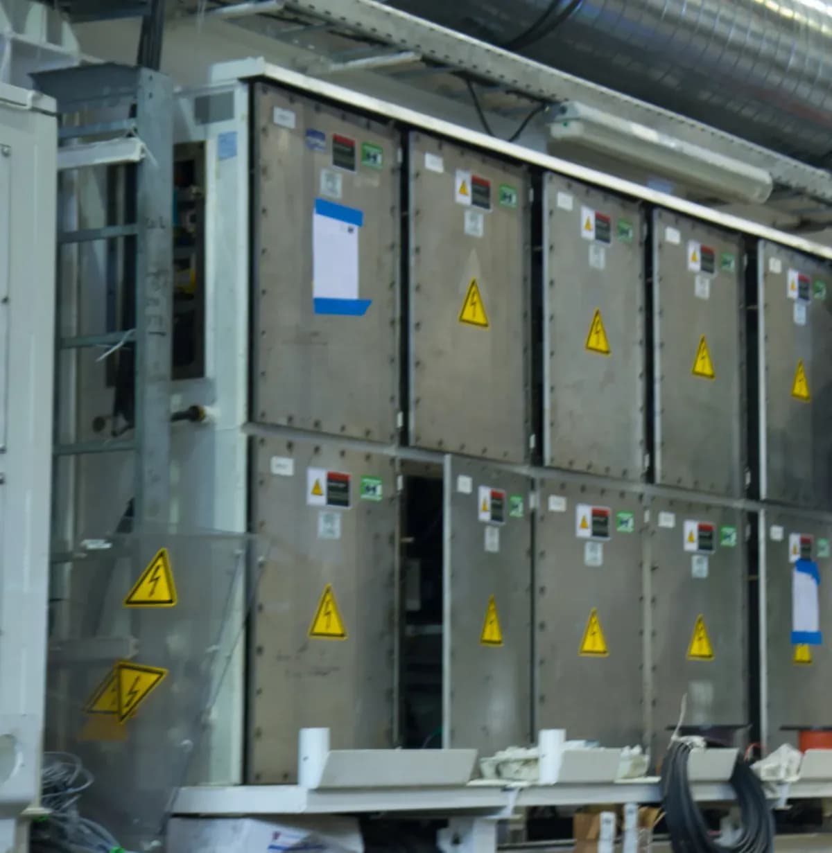
Electrical cabinets with high-voltage warning signs on a tunnel boring machine's trailing gantry, photographed during assembly. Photo: "ST U-Link TBM Electrical work" by Atomic Taco, CC BY-SA 2.0, via Wikimedia Commons, cropped.

Protecting the Cable in the Tunnel
Hang the cable high, cover it, or run it in covered trenches or protective pipes, and keep vehicles off it. Those routing options are the DGUV guide's examples for especially endangered cables. It also flags blasting and transport work as sources of higher mechanical stress on tunnel sites.
Fine dust combined with moisture can cause dangerous faults, and selected equipment needs at least IPX4 protection against splashing water. Cold matters too: insulation and sheath materials stiffen as temperatures fall and may turn brittle below their lower limit temperature. The guide highlights monthly tests of insulation monitoring and residual current devices (RCDs). Routine checks can reveal crushed cables and defective strain relief.
Safety bulletin SB25-02, published by the NSW Resources Regulator in March 2025, covers mobile plant hitting 11 kV cables in underground mines. Large mobile plant moving heavy loads hit HV cables in multiple incidents, causing cable damage and protection trips. Its recommendations say mine operators must clearly mark and secure HV cables, including solid protection where they cross active vehicle movement areas.
On US tunnel sites, 29 CFR 1926.800(s) requires power lines to be insulated or kept away from water, telephone or air lines or other conductive materials. Lighting circuits must be placed where moving people or equipment cannot damage them.
US underground metal and nonmetal mines must keep mobile equipment and dragged loads off power conductors unless the conductors are properly bridged or protected, under 30 CFR 57.12005. An MSHA fatality report covers a 2002 death in a TBM-driven water diversion tunnel at an Arizona copper mine. It names the cause as the lack of an effective low impedance grounding circuit for the 480/277 V tunnel lighting.
Fire Performance in Tunnels
Fire controls for tunnelling machines include a low fire load, fire resistant HV supply cables and cabinet fire suppression. The NSW draft code lists fire resistant hydraulic fluid and fire resistant power cables for the HV supply among its example TBM controls. It also lists fire detection and suppression in individual electrical cabinets. The draft does not apply to mining.
To keep fire load as low as possible, DGUV guidance says equipment must be chosen accordingly, for example flame-retardant or halogen-free material or cast-resin transformers. To keep wired safety systems working, materials and equipment need a defined functional integrity time, for example EI 30 to EI 90.
On 11 June 1994, fire broke out in one of four TBMs in the Great Belt Eastern Tunnel in Denmark. The abstract of a 1999 article says the cause is still unknown and hydraulic oil from the machine's hydraulic power system was the main fuel. All personnel were evacuated safely into the other tunnel.
The International Electrotechnical Commission (IEC) standard IEC 60332-1-2:2025 tests vertical flame propagation on a single insulated wire or cable, not circuit integrity in a fire. A pass on one cable does not show compliance with fire propagation requirements where cables are installed as a group. IEC 60754-1 determines halogen acid gas content, and IEC 60754-2 acidity and conductivity. Our low smoke zero halogen (LSZH) cable standards guide covers these tests.
Standards for TBM Cables
German DIN VDE cable standards cover trailing cable design, use and current ratings, while machinery, mine and tunnelling standards cover the surrounding equipment and sites. Our DIN VDE cable standards page introduces the wider German series.
- DIN VDE 0250-813:1985-05: trailing cable for power installation. Our TBM designs are based on it, as a design basis rather than a conformity claim.
- DIN VDE 0298-3:2006-06: guide to the use of non-harmonised cables.
- DIN VDE 0298-4:2023-06: recommended current-carrying capacity, including for flexible cables and cords.
- EN 16191:2014: tunnelling machinery safety requirements. It excludes services supplied to the machinery, such as power supply, water and compressed air.
- BS EN 50628:2016: erection of electrical installations in underground mines, published by the British Standards Institution (BSI).
- BS 6164:2019: UK code of practice for health and safety in tunnelling in construction, not intended for mineral-extraction shafts or tunnels.
Our TBM Cable Designs
Our two TBM reeling designs differ mainly in voltage range, earth construction and sheath options. The table compares the (N)TSCGECWÖU with the (N)TSCGECECWÖU TBM reeling cable.
- Feature: Rated voltage — (N)TSCGECWÖU TBM cable: 3.6/6 kV up to 18/30 kV — (N)TSCGECECWÖU: 3.6/6, 6/10, 8.7/15 and 12/20 kV
- Feature: Protective earth — (N)TSCGECWÖU TBM cable: Tinned copper and textile braid over each power core — (N)TSCGECECWÖU: Copper-wire screen over each core
- Feature: Control and monitoring — (N)TSCGECWÖU TBM cable: Three control cores; overall concentric monitoring conductor — (N)TSCGECECWÖU: Three control conductors; copper-wire monitoring screen over the inner sheath
- Feature: Insulation and sheaths — (N)TSCGECWÖU TBM cable: 3GI3 EPR insulation; GM1b EPR inner and red 5GM5 outer sheaths — (N)TSCGECECWÖU: Rubber insulation; red 5GM5 rubber sheaths, or a halogen-free version with a black polyurethane (PUR) outer sheath
- Feature: Movement data — (N)TSCGECWÖU TBM cable: Maximum tensile load 15 N/mm²; torsion ±25°/m; travel speed up to 30 m/min; S-type direction changes at least 20 × D apart — (N)TSCGECECWÖU: Torsion ±25°/m; minimum bending radius 6 × overall diameter fixed, 10 × flexed
- Feature: Fire tests listed — (N)TSCGECWÖU TBM cable: IEC 60332-1-2 — (N)TSCGECECWÖU: IEC/EN 60332-1-2; halogen-free version also IEC/EN 60754-1/2
- Feature: Design basis — (N)TSCGECWÖU TBM cable: Based on DIN VDE 0250-813 — (N)TSCGECECWÖU: Lists VDE 0250 Part 813, VDE 0295 and EN 60228
Our (N)TSCGECECWÖU datasheet for 8.7/15 and 12/20 kV gives layer currents for 3x120 mm² at 30 °C ambient. The sheet lists 371 A on the floor, 297 A with one reel layer and 141 A with five. The chart plots the floor value and all five layer values.
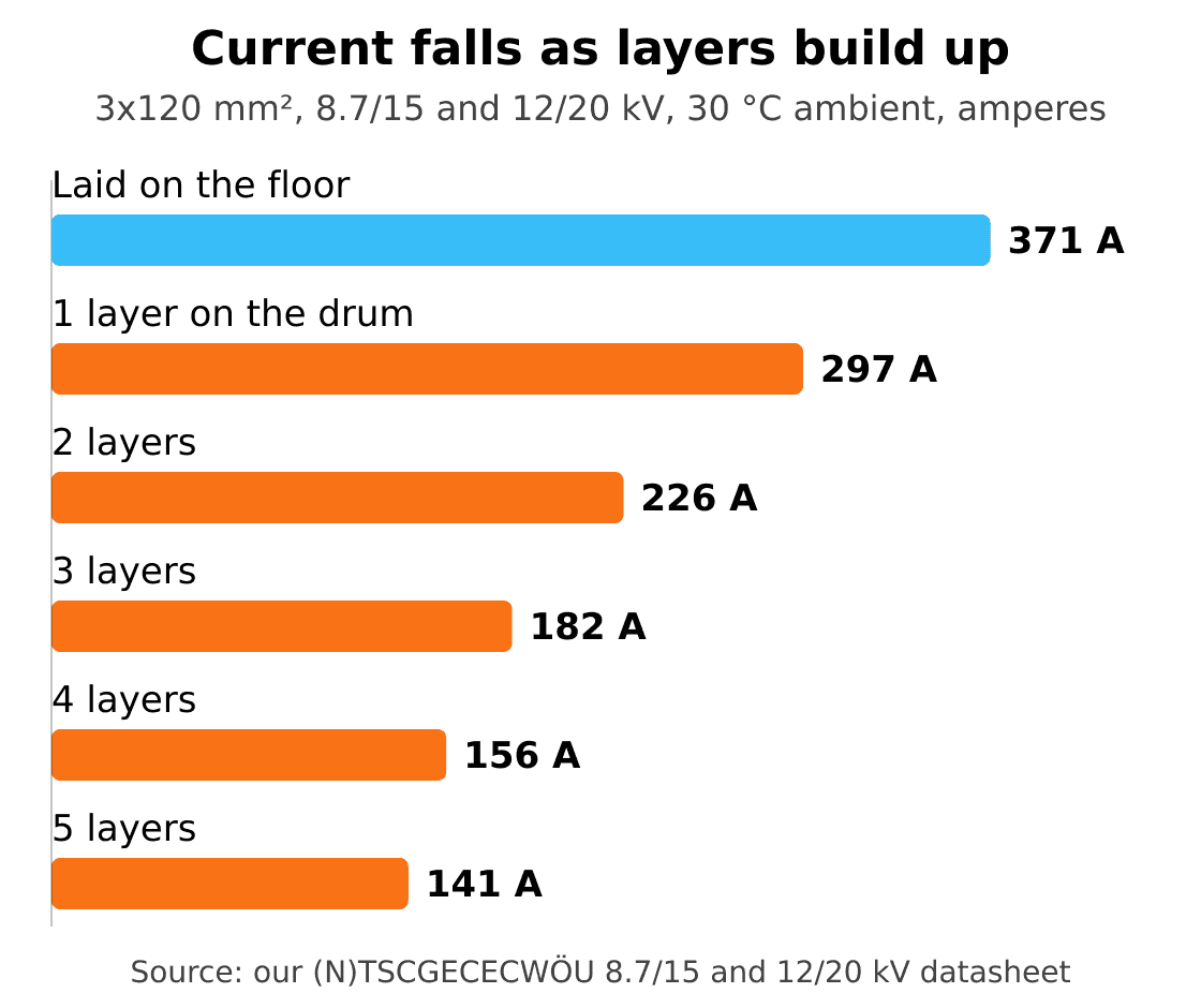
Current-carrying capacity of our 3x120 mm² (N)TSCGECECWÖU at 8.7/15 and 12/20 kV, at 30 °C ambient, from its datasheet. It falls from 371 A laid on the floor to 297 A with one layer on a drum and 141 A with five layers. Other sizes, voltages and temperatures have their own datasheet values.
Current-carrying capacity in amperes of a 3x120 mm² (N)TSCGECECWÖU cable at 8.7/15 and 12/20 kV and 30 °C ambient, from our datasheet. Laid on the floor: 371 A. On a drum: 297 A with 1 layer, 226 A with 2, 182 A with 3, 156 A with 4 and 141 A with 5.
Our product pages and datasheets are design references, not approval or conformity certificates. The approval each jurisdiction requires is confirmed per order.
How to Specify a TBM Cable
Start with the supply and the route, then work through the cable's construction and the local rules. For drive circuits on the machine itself, see our mine variable frequency drive (VFD) cable guide.
- Supply: voltage, the TBM transformer and the machine's power demand.
- Feed method and route: reel on the machine, cable store or dragged, plus the route length.
- Conductor size: rated for reel layers, ambient temperature and voltage drop over the route.
- Earth, control and monitoring: an architecture that matches the monitoring device and couplers.
- Couplers and junction boxes: interlocked so they open or separate only when dead.
- Movement limits: tension, torsion, travel speed, direction changes and bend radius.
- Fire and environment: halogen-free sheath option, flame tests, water, dust and cold.
- Local rules: DGUV in Germany and Austria, OSHA for US tunnels, MSHA Part 57 for US underground metal and nonmetal mines, NSW guidance.
Frequently Asked Questions
What voltage do TBM cables run at?
A TBM cable carries the machine's supply voltage, which DGUV guidance says is mostly HV, for example 6 to 20 kV. The guide notes that tunnel sites often use HV installations of currently up to 20 kV. The cable's rated voltage must suit the site's actual supply.
What does the monitoring conductor in a TBM cable do?
The monitoring conductor lets protection detect a broken protective conductor and trip the supply. DGUV guidance says monitoring the protective conductor for a break needs a separate monitoring conductor. Junction-box and plug interlocks can, for example, open this circuit so connections separate only when dead.
How is the cable fed as the TBM advances?
A TBM cable can be fed from a reel on the machine, from a cable store or drum, or laid out and dragged, as DGUV guidance describes. A reel coupled to the travel drive pays out going forward and winds in going back, with no significant tensile forces.
Can a TBM cable be dragged instead of reeled?
Yes, a TBM cable can be dragged: DGUV guidance lists it as an option, but large tensile forces and damage from vehicles and plant are possible. It recommends a tensile-resistant armoured cable and, where the machine has no cable drum or similar measure, a tension limiter.
Do TBM cables have to be halogen-free?
Halogen-free sheaths are one option for TBM cables, not the only one: DGUV guidance gives flame-retardant or halogen-free material as examples for keeping fire load low. The NSW draft code lists fire resistant power cables for the HV supply among TBM fire controls. Confirm the project's fire specification first.
Which standards apply to TBM cables?
DGUV guidance points to the VDE 0298 series for cable use in Germany and Austria, and DIN VDE 0250-813 is the German trailing cable standard. EN 16191 covers tunnelling machinery but excludes the power supply to it. In the US, OSHA rules govern tunnel construction and MSHA Part 57 covers underground metal and nonmetal mines.
Enquire About TBM Cable
For a TBM cable enquiry, our engineering team needs the supply voltage and power, the feed method and reel drawing, the route length and the conductor size. Add the earth, control and monitoring arrangement, the coupler type, fire requirements, ambient conditions and the rules that apply where you work. Send them through our contact page.
About the Author
Jyen is a technical and operations engineer at TEBAOFLEX, responsible for the company's online platforms. This guide draws on German and Austrian tunnelling guidance, US federal construction and mine safety rules, New South Wales guidance and a safety bulletin, standards catalogue records and TEBAOFLEX product datasheets. The product pages cited are TEBAOFLEX's own; requirements quoted from regulators and standards bodies describe their scope, not certification or approval of our products.
Cover photo: tunnel boring machine back-up at the U2 Pilgramgasse station works in Vienna, by wdwd, CC BY-SA 4.0, via Wikimedia Commons, cropped.
