


A reeling cable is a flexible power, control or data cable built to wind onto and off a cable reel as a crane, stacker-reclaimer or other travelling machine moves. Seven factors decide its selection: reel arrangement, travel speed and acceleration, tension, bending radius, torsion, current derating on the drum, and the construction and standard. For festoon, trailing and drag-chain cables, see special cables and their standards. Ports also use reeling cables on shore-power cable reels.
The EU Alternative Fuels Infrastructure Regulation sets a 31 December 2029 shore-power deadline. It covers container and passenger ships in Trans-European Transport Network maritime ports, based on port activity levels. A European Environment Agency assessment published on 10 February 2026 found shore power at 71 of 179 core network ports.
Key Takeaways
- Identify the reel's drive, winding pattern and feed point first; each changes how the cable is loaded.
- Permitted pull is the permissible tensile stress times the conductor cross-section the datasheet counts; DIN VDE 0298-3 sets 15 N/mm² for flexible cables.
- Derate current for each complete layer; German and US factors apply to different base ratings, so compare resulting currents, not factors.
- Check every drum, pulley and guide against the datasheet's minimum bending radius, stated as a multiple of the cable's outside diameter.
Step 1: Identify the Cable Reel Arrangement
Every reel combines a drive (motor or spring), a winding pattern (monospiral or level-wind) and a feed point (end or centre). Each changes how the cable is loaded, so identify all three first.
- Choice: Winding pattern — Option: Monospiral — What to check: Torque changes with coil diameter and peaks with a full reel under acceleration (Kostić et al., 2017)
- Choice: Winding pattern — Option: Level-wind (multi-layer) — What to check: Helices on drums about 1 to 3 m in diameter and up to 6 m long; stacked layers lower the current rating (Conductix-Wampfler; see Step 6)
- Choice: Drive — Option: Motor-driven — What to check: Drive sized from travel speed and acceleration (VAHLE catalogue)
- Choice: Drive — Option: Spring-driven — What to check: Keep at least two full wraps on the drum at maximum extension, which the Conductix 1400 series manual says avoids excessive tension on the cable and prevents pull-out at the entrance
- Choice: Feed point — Option: Centre feed — What to check: Operational cable length is half the travel length (VAHLE catalogue)
Step 2: Define Travel Speed and Acceleration
Specify both travel speed and acceleration: reel makers size the drive from the two, according to the VAHLE motor-powered reel catalogue. Its selection questionnaire asks for travel speed in m/min and acceleration in m/s², plus cycles per hour, operating hours per day and duty cycle. On a monospiral reel, Kostić et al. (2017) show that torque peaks while winding under acceleration when the reel is full, that is, when the machine is closest to the cable's fixed connection point. The drive must therefore control torque.
The HVR medium-voltage (MV) reeling cable is rated for travel speeds up to 180 m/min, with higher speeds on request. The TRA-RF low-voltage (LV) spreader reeling cable is rated up to 200 m/min in horizontal and vertical reeling. These are datasheet values for those two cables, not general limits.
Step 3: Calculate the Tension
The permitted pull on a reeling cable equals the permissible tensile stress multiplied by the conductor cross-section that the datasheet counts. DIN VDE 0298-3 sets 15 N/mm² for the conductors of flexible cables, as reproduced by cable distributor Koch KT. Reinforced reeling designs carry higher datasheet ratings: 20 N/mm² for HVR, 25 N/mm² for the (N)TSCGEW11Y shore-power reeling cable and 30 N/mm² for TRA-RF.
Worked examples:
- H05VV-F 4G2.5 cord (Koch KT's DIN VDE 0298-3 example): all four cores count, so 15 N/mm² × (4 × 2.5 mm²) = 150 N maximum pull.
- NTSCGEWÖU 3×70 + 3×35/3: the three 70 mm² phase conductors count, not the split earth conductors, so 15 N/mm² × 210 mm² = 3,150 N on the NTSCGEWÖU datasheet.
- TRA-RF 24×2.5: all 24 cores count, so 30 N/mm² × 60 mm² = 1,800 N on its datasheet.
The set-point tension is the tension the reel drive holds at standstill. It comes from the hanging cable weight: F = m′ × L × g (mass per metre × hanging length × gravitational acceleration). Kostić et al. (2017) calculate about 299 N for 6.1 kg/m over 5 m. Keep the highest tension the reel drive applies, including during acceleration and braking, under the permitted pull. The VAHLE catalogue offers a limit switch that stops the drive when the last or next-to-last winding unwinds.
Step 4: Check Bending Radius and Guide Geometry
Every drum, pulley and guide on the cable path must respect the cable's minimum bending radius, given as a multiple of its outside diameter (D). For LV cables, DIN VDE 0298-3 as reproduced by Koch KT sets 5 × D on a drum up to 20 mm outside diameter and 6 × D for larger diameters. Over pulleys, the minimum is 7.5 × D.
The (N)TSCGEW11Y datasheet lists 6 × D in fixed installation, 10 × D in free movement and 12 × D for reeling, double the fixed value. The HVR datasheet also lists 12 × D on the reel, 15 × D over deflection pulleys and 20 × D for an S-type change of direction (two consecutive bends in opposite directions).

Source: (N)TSCGEW11Y and HVR reeling cable datasheets, 2026.
On motor-driven reels, the VAHLE catalogue limits diagonal pull onto the reel to 3°. The Conductix 1400 series manual, for spring-driven reels, allows up to 15° either side of the drum centre line, beyond which it calls for a pivot base. Use the limit in your reel maker's manual.
Step 5: Limit Torsion
Limit torsion by installing the cable without twist and choosing a construction that absorbs what remains. On motor-driven reels, the VAHLE catalogue requires the cable on the reel body to be free from twisting, while allowing for safety windings for strain relief.
For spring-driven reels, the Conductix 1400 series manual traces twisting or knotting to improper installation, rubbing on or bending around fixed objects, excessive spring tension or poor anchoring. It calls for mounting the roller guide so the cable travels perpendicular to the axis of rotation, which guards against twisting. When wrapping the cable onto the reel, do not let it twist or loop.
The HVR datasheet describes a high-tensile synthetic-yarn braid, vulcanised between the inner and outer sheaths, that absorbs ±25°/m of twist without passing it to the cores. The NTSCGEWÖU datasheet specifies a polyester anti-torsion braid for the same purpose.
Step 6: Derate the Current for the Drum
A cable coiled on a drum sheds less heat than a straight run, so derate its current rating for every complete layer. The DIN VDE 0298-4 reduction factors, as reproduced in the VAHLE catalogue, are 0.80, 0.61, 0.49 and 0.42 for one to four complete layers. The one-layer factor also applies to monospiral coils.
The US Mine Safety and Health Administration (MSHA) reports a second set, from the Insulated Cable Engineers Association (ICEA), in Program Information Bulletin P10-20. ICEA ampacity tables derate cable on a reel to 85, 65, 45 and 35 per cent for one to four layers. In its evaluations, MSHA assumes that layers are periodically removed from the reel so the whole length can cool. A 1994 US Bureau of Mines study found that ICEA and National Electrical Manufacturers Association (NEMA) reel factors did not give conservative conductor temperatures for the cable designs it tested.
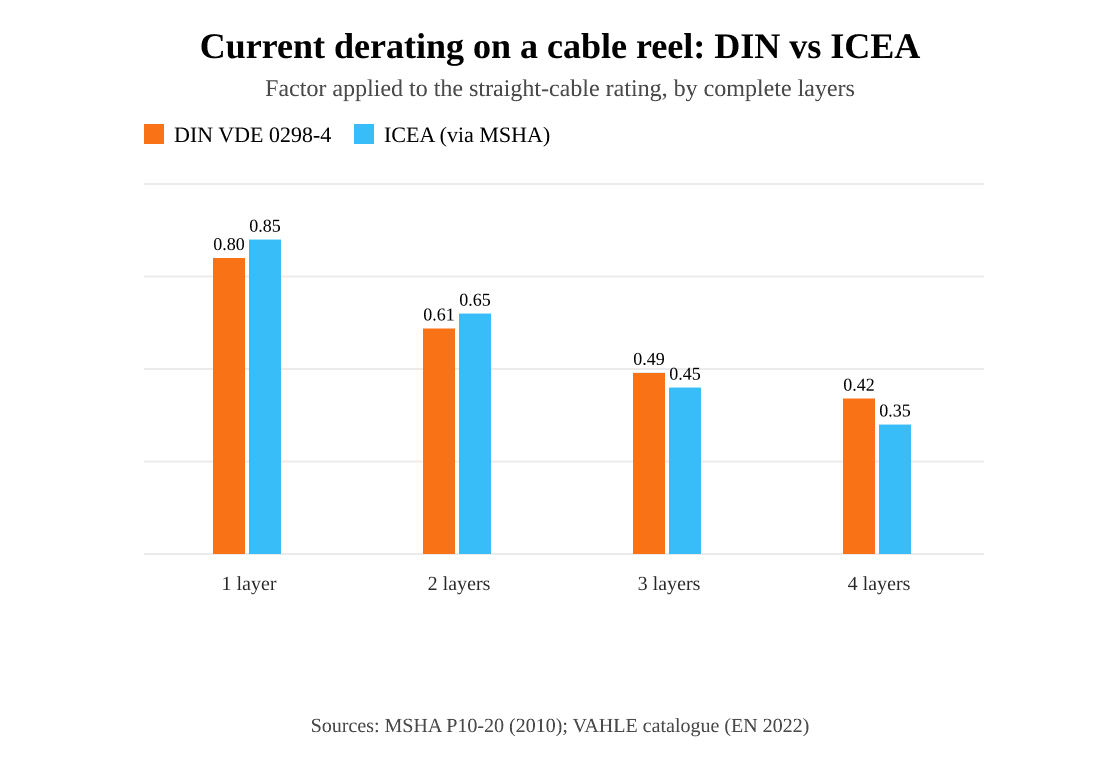
Source: MSHA bulletin P10-20 (2010); DIN VDE 0298-4 values reproduced in the VAHLE catalogue (EN 2022). Different base current ratings apply.
DIN VDE 0298-4 factors are lower for one and two layers, ICEA factors for three and four. Each factor applies to its own standard's base current rating, so compare the resulting currents rather than the factors, and confirm them with the cable maker.
Step 7: Choose the Construction and Standard
Choose the construction by voltage, the signals the reel must carry and the site's rules, then confirm its standard.
- Duty: LV power — Construction: NSHTÖU low-voltage reeling cable, 0.6/1 kV, class 5 conductors — Standard or rule: DIN VDE 0250-814
- Duty: MV power — Construction: NTSCGEWÖU — Standard or rule: Based on DIN VDE 0250-813
- Duty: Shore power — Construction: (N)TSCGEW11Y, screened 6/10 kV, optical element with 12 fibres — Standard or rule: References IEC/ISO/IEEE 80005-1 and DIN VDE 0298-3 and 0298-4
- Duty: Mining, Western Australia — Construction: Pilot core arranged to cut off the supply if the earthing circuit breaks — Standard or rule: AS/NZS 2802:2000 (WorkSafe WA)
IEC 60228:2023 defines class 5 (flexible) and class 6 (extra flexible) conductors. For cranes, IEC 60204-32 covers the electrical equipment of hoisting machines.
The HVR datasheet specifies a 5GM5 heavy-duty chloroprene rubber outer sheath that is flame-retardant and resistant to oil, ozone, ultraviolet light and abrasion. The cable is rated −30 °C to +80 °C ambient when flexing. The TRA-RF datasheet specifies a highly abrasion-resistant double polyurethane (PUR) sheath and a rating of −25 °C to +60 °C when flexing.
A composite reeling cable puts power, control and data in one sheath. For a port crane in Vladivostok, the specified 6/10 kV reeling cable combines three 35 mm² power cores, earth conductors, sixteen 2.5 mm² control cores and an optical unit with 24 fibres.
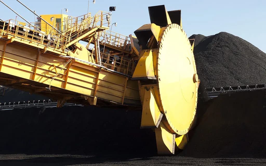
Stacker-reclaimers on bulk terminals are a classic reeling-cable application. Photo: "Coal reclaimer at Newcastle Port close up" by Jeremy Buckingham MLC, CC BY 2.0, via Flickr.
Retrofits add a size limit. A tender at a coastal coal-fired power plant in Vietnam aimed to replace the MV reeling cable on its existing reel equipment. Samples of its two 8.7/15 kV constructions had to fall within outside-diameter windows of 56 to 59 mm and 62 to 65 mm. The same tender specified 8 × D static and 12 × D dynamic bending radius and a −40 °C to 90 °C service range.
Reel-Related Warning Signs
Watch for two signs: heat damage near the inner layers, and twist. MSHA notes that reel heating is most noticeable when three or four layers remain on the reel. After heavy duty, check the sheath on the inner layers for overheating damage.
Safety: stop the equipment and isolate electrical power before inspecting or handling the cable. Have qualified personnel control stored mechanical and spring energy under the reel manufacturer’s procedure. Assess cable damage before any correction or return to service.
If the cable twists, turn the twists back out, then check the reel, guide and anchoring against the torsion causes in Step 5.
What to Send With an Enquiry
Send the cable model, voltage, conductor size and quantity, as the TEBAOFLEX reeling cable enquiry form asks. For reeling duty, also give the equipment, reel arrangement, travel distance, speed and tension. Then add:
- Feed point, such as centre feed
- Acceleration in m/s², cycles per hour and duty cycle
- Drum diameter and number of layers
- Radii of the pulleys and guides, and any S-type change of direction
- For retrofits, the outside-diameter window of the existing equipment
- Environment: temperature range and exposure to water or oil
- Required standards and approvals, such as DIN VDE 0250-813 or AS/NZS 2802:2000
Frequently Asked Questions
What is the minimum bending radius of a reeling cable?
A reeling cable's minimum bending radius depends on its voltage and construction and is given as a multiple of its outside diameter (D). On a drum, DIN VDE 0298-3 gives 5 × D or 6 × D for LV cables, depending on diameter (Koch KT), while the HVR and (N)TSCGEW11Y MV datasheets list 12 × D.
How much tension can a reeling cable take?
The permitted pull on a reeling cable is its permissible tensile stress multiplied by the conductor cross-section its datasheet counts. At the DIN VDE 0298-3 value of 15 N/mm², the NTSCGEWÖU 3×70 + 3×35/3 datasheet lists 3,150 N. The reinforced HVR, (N)TSCGEW11Y and TRA-RF datasheets list 20, 25 and 30 N/mm².
Can one cable reel carry more than one cable?
A cable reel typically carries only one cable, according to the MHI Overhead Alliance. A reel that needs power, control and data therefore usually uses a composite reeling cable, such as the 6/10 kV cable with an optical unit with 24 fibres specified for a port crane in Vladivostok.
Specify Your Reeling Cable
A reeling cable that suits its reel starts with complete duty data. Send the reel arrangement, travel data, drum geometry and required standards to our engineering team through the contact page for a selection review.
About the Author
Jyen is a technical and operations engineer at TEBAOFLEX, responsible for the company's online platforms. This guide draws on the standards, regulations and datasheets cited above and on project records published in the TEBAOFLEX case library. The HVR, TRA-RF, NSHTÖU, NTSCGEWÖU and (N)TSCGEW11Y datasheets cited are TEBAOFLEX's own product pages.
Cover photo: "Power cable reel on a crane" by Sam Wilson, CC BY-SA 2.0, via Wikimedia Commons, cropped.
